Hello. This is my first time asking a question on the forum but I've read many so I'll try to be thorough.
I'm trying to use a stepper motor with integrated driver to move a platform to desired angles. I've previously used a stepper with a separate driver, so I understand how to use the Step (X1), Direction (X2), and Enable (X3) inputs to produce the desired motion.
This motor also has RX & TX connections, though, and I'm not sure if I also need to connect those somewhere. Are those only used when connecting via RS-422/485? Will they send back information from the servo? If the Step, Dir, Ena wires produce the desired motion, is it acceptable to leave the RX/TX wires unconnected?
Other details about the project: I'm also using the arduino to collect information from a CUI AMT20 Series encoder via the ICSP pins. I'm pretty new to all of these systems so tips/tutorials would be appreciated.
Looks like you need to use phototransistor output opto couplers on the inputs, emitter to V-, collector to the relevant pin (X1/step, X2/dir). The controller inputs are 24V so direct connection is not possible.
Read the relevant bits of the user manual a couple of times, this is normally the way to grok a complex
piece of machinery like this - take notes.
You need to set it up in position control mode and I/O mode step/direction - I presume their software will
allow this.
MarkT:
Looks like you need to use phototransistor output opto couplers on the inputs, emitter to V-, collector to the relevant pin (X1/step, X2/dir). The controller inputs are 24V so direct connection is not possible.
I believe you may be referencing the diagram labeled "Connecting to a Controller with Sinking Outputs." I was going to follow along the lines of the one further down labeled "Connector Controlled with Differential Outputs," with X1 (STEP), X2 (DIR), and also X3 (ENA) connected to pins 5-7 and their respective negatives to GND. The Arduino pins don't put out 24V so that wouldn't be an issue. Does this setup not qualify as differential outputs? I didn't think Sinking Outputs applied to this situation.
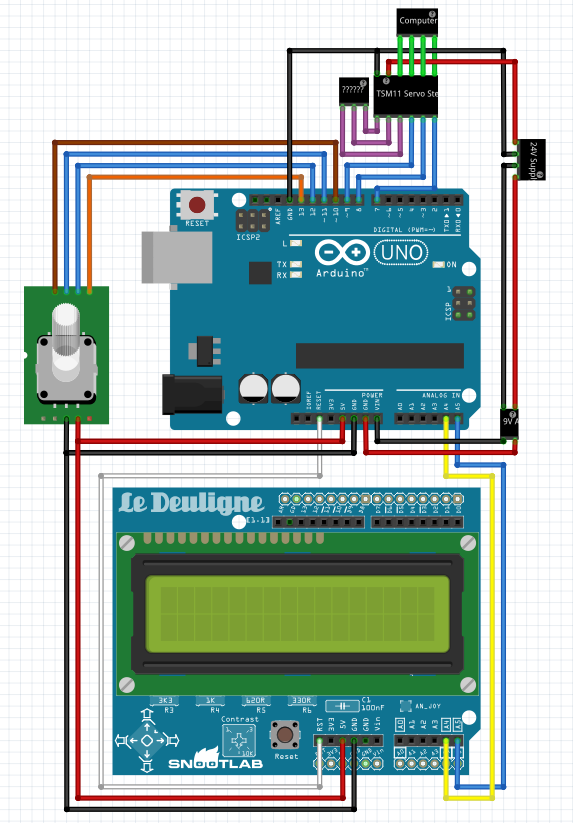
I've made a wiring diagram that I hope will help to clarify.
MarkT:
You need to set it up in position control mode and I/O mode step/direction - I presume their software will
allow this.
So once I've set the mode to step/direction in the setup software, do I need to maintain the TX/RX connection? I intend for this system to operate independent of a computer so I was hoping the Arduino program could operate it.
Yes, reading it agains those pins are inputs only, so opto isolation isn't needed - some of the other pins can be configured as outputs and they need to be treated with care.
Have you tried programming the unit yet - the software is likely to be the final arbiter of what's possible
if the documentation doesn't say and you don't want to talk to the manufacturer directly - usually people
are willing to clarify such details if it leads to a sale.
I started experimenting in the software as soon as I received the RS-422/485 to USB converter. It will only respond predictably to the sample button meant for tuning. I've tried configuring it in "Pulse & Direction" mode and "CW & CCW Pulse" mode, but it won't respond to the pulses from Arduino.
The most successful result I got was in CW/CCW mode with this sketch:
This still didn't step to a beat. I tried attaching a video but it wouldn't work. It was kind of like 1 short step followed by 2 long ones, then a pause, then a similar sequence. I'm not sure why a delay during the step changed anything, but when I took it out the steps were seemingly random with 1-10 seconds between them.
Something to note is that I've had the RS-244/485 converter connected to my computer at the same time as the Arduino. I disconnected the converter to see if that was why it wouldn't respond to the pulses, but after this it just wouldn't move no matter what I sent it. According to the status light it was still enabled and the shaft still resisted manual turning. It only started working again when I restarted the program, re-connected the converter, and power cycled the motor. Why would it have stopped responding?
I realized that I hadn't connected the motor ground (V-) to the arduino ground which improved things considerably. I'm now using an adaptation on the Sweep example sketch, with the HI/LOW value sent to X2 determining the direction of rotation as I've used before for stepper motors. However, instead of moving 180 degrees back and forth it's making full continuous circles at a constant speed. Neither the speed nor the travel change when I change the maximum value of pos or the delay.
As a side note, does anyone have an explanation for what it means that this is a Servo-Stepper motor as opposed to just a servo or just a stepper? It doesn't behave like a standard stepper, servo, or even a continuous rotation servo so I'm having trouble finding relevant resources.
Sorry to post so many updates in succession. The pressure's really on to get this project working and I'm at a loss for what's wrong and where to find resources. This motor is starting to feel like an expensive paperweight.
Right now I can't get the motor to turn to the angle I tell it. It goes slightly less (ie. I tell it 180 and it goes about 120, 90 it goes maybe 75?) and it does so very slowly when I need to move the platform 20 degrees/second. I tried to figure out how to read the angle from the motor (Y1/Y2) to maybe make my own feedback loop but the manual doesn't give any indication that you can do that and I can't find resources on it anywhere so I think that might be a dead end.
In summary, hot questions:
What resources are available/what does it mean that this is a step-servo motor as it does not behave like a standard stepper motor, servomotor, or continuous servomotor?
How do I get it to move to a specified angle reliably and precisely? Or in what way am I doing that wrong?
How can I control the speed at which it rotates/steps?
How do I use a "general purpose output" (or any other method) to read the motor's angle? Or isn't it possible?
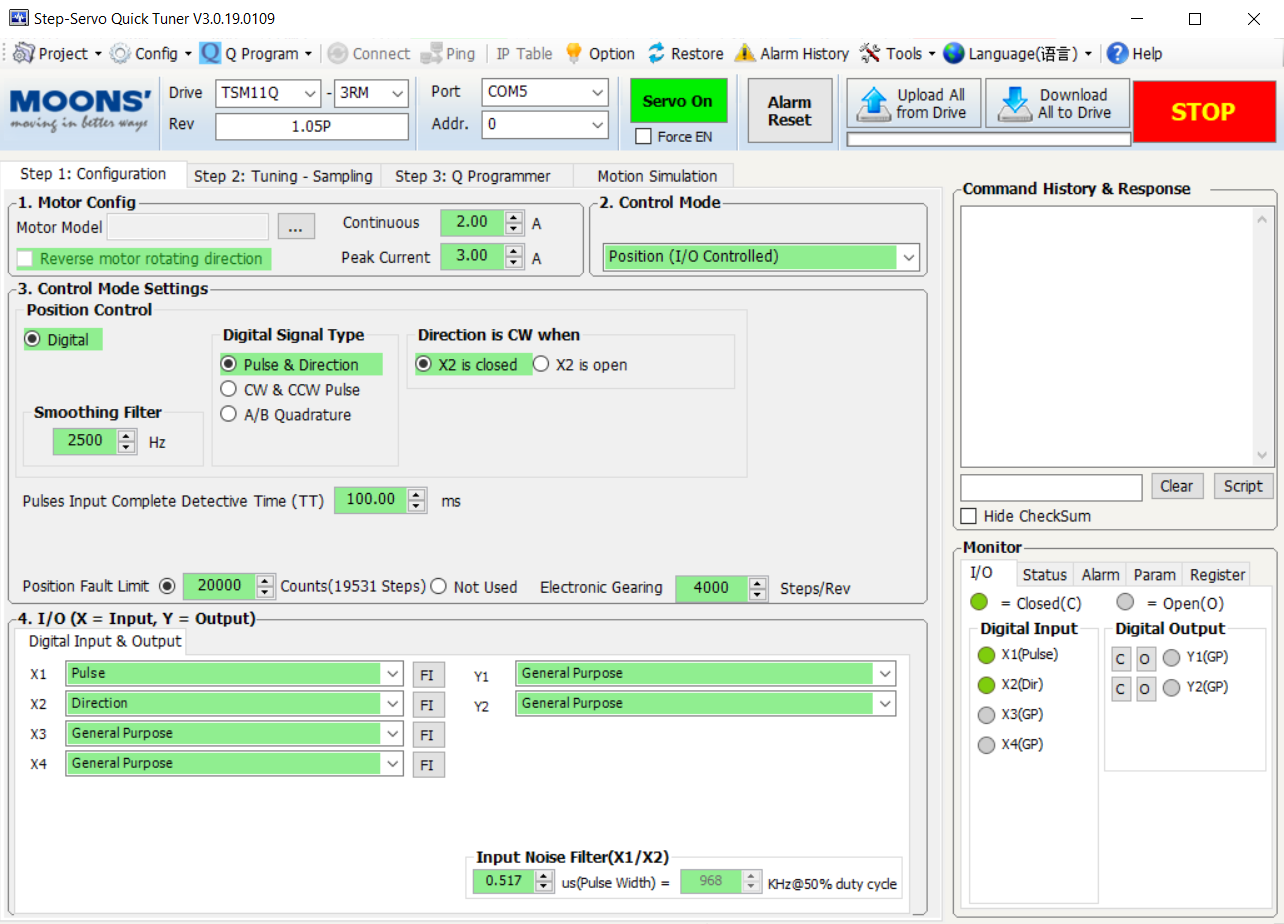
I've attached updated schematic, sketch, and motor configuration parameters. Again, sorry to be so naggy, I just know that this forum is my best chance at finding solutions.
Based on the documentation, the machine appears to be an actual servo motor that can be programmed to have as many stepper motor steps as required. That number of steps must be part of the configuration set-up.
Can you elaborate at all? Does that mean that I can't program it with Arduino, only the provided software? Or if it's "an actual servo motor" does that mean that I should be using the Servo library? And if so is the value I use still the duty cycle, or does it change to be the number of steps?
Kaitlyndasilva:
Can you elaborate at all? Does that mean that I can't program it with Arduino, only the provided software? Or if it's "an actual servo motor" does that mean that I should be using the Servo library? And if so is the value I use still the duty cycle, or does it change to be the number of steps?
Anything you can do with the PC software, you can do with an Arduino. It is up to you to learn all that the PC software does and how it affects the device. And you need to REALLY understand the documentation. We can't do that for you. You have the devices and we don't, nor do we have the time to learn.