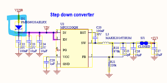
I measured unexpectedly high reverse leakage currents through the Schottky diode D2 that are way out of specs of the PMEG6020AELRX diode specified in the schematic.
I supply 5V to VIN and have the USB-C port and all other pins unconnected (except GND). I connect a 1k pull-down resistor between GND and VUSB and measure a voltage drop of ~1V accross that resistor. The reverse leakage is thus around 1mA.
According to the datasheet of PMEG6020AELRX the reverse leakage at 5V and 25°C should be <100nA. This is 4 orders of magnitude smaller than what I measure.
I can reproduce this on both official Arduino Nano ESP32 boards I own. I also verified with other resistance values from 330R to 44kR. All show reverse leakage in the range of 0.1 to 1mA.
It seems like D2 is not PMEG6020AELRX as specified in the schematics.
Could someone from the Arduino hardware team comment on this? Are there board revisions with a different diode model mounted?
In the real world, documentation is written long before any production is started. Things may happen and components may change during production. In any case, the engineer doing the design is rarely consulted by the person writing the documentation. They may be long gone from the company.
Are you sure it's the diode, and not some other path.
Did you measure voltage on VUSB without the bleed resistor.
It would only worry me if VUSB (open circuit) increases beyond 5volt with more than 5volt on Vin.
Leo..
I realise that. Most DMMs have a 10Megohm impedance.
2.7volt makes me think that some current is bleeding from the processor 3.3volt supply to the serial chip. I think you worry about nothing.
Leo..
Could find this out by desoldering D2 and checking again, but I want to keep my boards intact for now
Maybe someone else can do this experiment?
It actually annoyed me a lot. I designed some power-source selective enable-logic of downstream circuits based on the voltage on VBUS with pull-down connected. The cicuit should automatically enable when USB-C is plugged, but not when power is supplied directly to VIN. My design was assuming the leakage current would not exceed 1uA. The circuit failed miserably
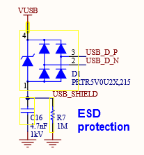
Oha USB 2.0 D+ lane is specified at 3.3V with 1.5k pull-up in idle state. Consistent with 2.7V after ESD diode (0.6V drop). And also consistent with 1.5V when connecting 1.2k pull-down.
Looks like the D+ ESD diode is the guilty guy and not D2