@PaulRB Is this what you meant? Assuming I can use all 4 of those IC2 pins at once ![]()
Yes that's fine. Physically you are connecting the 2 i²c devices to separate pins, but electrically they are the same pins, they connect back to the same 2 pins on the atmega chip.
Thank you so much, you have no idea how many hours of my day I've spent trying to get my brain around this! I really appreciate your input, as you've helped solve the last two issues with the circuit ![]() I can't wait to finally build it tomorrow
I can't wait to finally build it tomorrow
1 Like
Is it possible you connected the level shifter incorrectly? We can't tell from your diagram because the pins are not labelled.
@
Your two topics on the same or similar subject have been merged.
Please do not duplicate your questions as doing so wastes the time and effort of the volunteers trying to help you as they are then answering the same thing in different places.
Repeated duplicate posting could result in a temporary or permanent ban from the forum.
Could you take a few moments to Learn How To Use The Forum
It will help you get the best out of the forum in the future.
- Your OS and version can be valuable information, please include it along with extra security you are using.
- Always list the version of the IDE you are using and the board version if applicable.
- Use quote or add error messages as an attachment NOT a picture.
- How to insert an image into your post. ( Thanks @sterretje )
- Add your sketch where applicable but please use CODE TAGS ( </> )
- Add a SCHEMATIC were needed even if it is hand drawn
- Add working links to any specific hardware as needed (NOT links to similar items)
- Remember that the people trying to help cannot see your problem so give as much information as you can
COMMON ISSUES
- Ensure you have FULLY inserted the USB cables.
- Check you have a COMMON GROUND where required. ( Thanks @Perry)
- Where possible use USB 2.0 ports or a USB 2.0 POWERED HUB to rule out USB 3.0 issues.
- Try other computers where possible.
- Try other USB leads where possible.
- You may not have the correct driver installed. CH340/341 or CP2102 or FT232 VCP Drivers - FTDI
- There may be a problem with the board check or remove your wiring first.
- Remove any items connected to pins 0 and 1.
COMPUTER RELATED
- Close any other serial programs before opening the IDE.
- Ensure you turn off any additional security / antivirus just to test.
- There may be a problem with the PC try RESTARTING it.
- You may be selecting the wrong COM port.
- Avoid cloud/network based installations where possible OR ensure your Network/Cloud software is RUNNING.
- Clear your browsers CACHE.
- Close the IDE before using any other serial programs.
- Preferably install IDE’s as ADMINISTRATOR or your OS equivalent
ARDUINO SPECIFIC BOARDS
- CH340/341 based clones do not report useful information to the “get board info” button.
- NANO (Old Types) some require you to use the OLD BOOTLOADER option.
- NANO (ALL Types) See the specific sections lower in the forum.
- NANO (NEW Types) Install your board CORE’s.
- Unless using EXTERNAL PROGRAMMERS please leave the IDE selection at default “AVRISP mkII”.
- Boards using a MICRO usb connector need a cable that is both DATA and CHARGE. Many are CHARGE ONLY.
CREATE editor install locations.
- On macOs ~/Applications/ArduinoCreateAgent-1.1/ArduinoCreateAgent.app/Contents/MacOS/config.ini
- On Linux ~/ArduinoCreateAgent-1.1/config.ini
- On Windows C:\Users[your user]\AppData\Roaming\ArduinoCreateAgent-1.1
Performing the above actions may help resolve your problem without further help.
Language problem ?
Try a language closer to your native language:
- 中文 (Chinese)
- Deutsch - German
- Español - Spanish
- Français - French
- অসমীয়া, বাংলা, बड़ो - India
- Italiano - Italian
- Nederlands - Dutch
- Portugues - Portuguese
- Россия - Russia
- Scandinavia Swedish, Suomi - Finnish, Norsk - Norwegian
Thanks to all those who helped and added to this list.
Thank you.
Not this one! It has a 3.3V regulator of its own.
I'll post some photos of both boards wired up as soon as I can, it'll be in an hour or so as I'm out of the house right now, thank you for your input though!
Connected as described here?
UNO
AVCC: 5V VCC ← connected to UNO's 5V pin
ASCL: 5V SCL ← UNO's A5 pin
ASDA: 5V SDA ← UNO's A4 pin
AGND: 5V GND ← UNO's GND pin
nunchuk
BVCC: 3V VCC ← connected to UNO's 3.3V pin unconnected
BSCL: 3V SCL ← nunchuk
BSDA: 3V SDA ← nunchuk
BGND: 3V GND ← nunchuk
Yeah I was trying to follow that as it's in the amazon listing description. I did it a few times just to check I hadn't done it wrong, but had no luck sadly
I think that may be incorrect...
As I mentioned above, this level shifter board has its own regulator:

This isn't the exact same board and I can't find a schematic for it. But I think it does not need a connection to the Uno's 3V3 pin.
1 Like
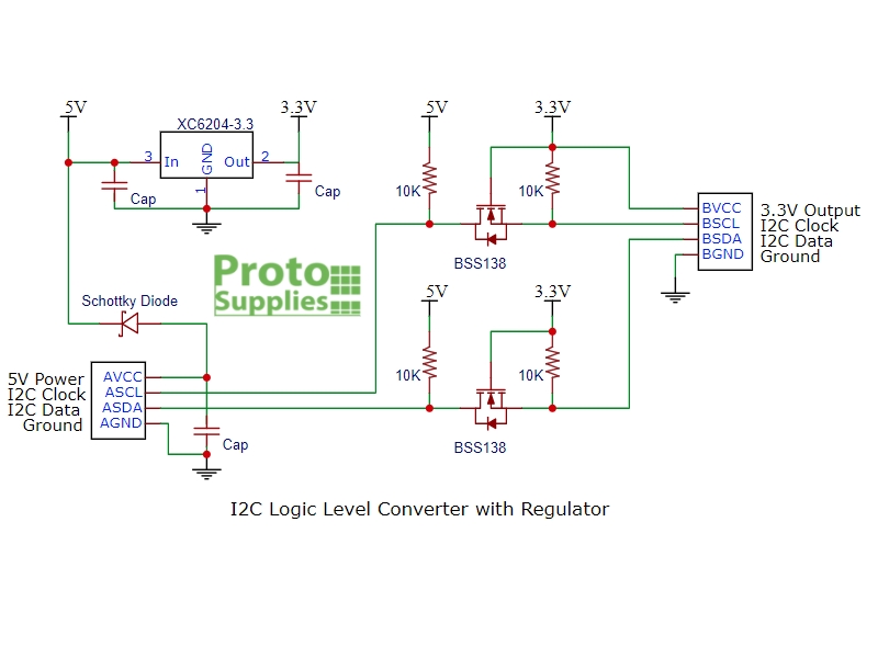
I think this may be it.


yes, that looks identical to the one I bought! the connector for the nunchuck has 4 pins too, Clock, data, + and -
I agree! (thanks). The manufacturer's link is misleading ...
The level converter is very easy to use. The board needs to be powered from the two voltages sources (high voltage and low voltage) that your system is using. High voltage (5V for example) to the 'HV' pin, low voltage (3.3V for example) to 'LV', and ground from the system to the 'GND' pin.
Based on this schematic and images, the converter's 3.3V output should be left disconnected.
I've corrected my previous post by striking out this connection.
Should I then attach the ground from the nunchuk board directly to the uno to complete the circuit?
Yes. (you may have just found the real problem) ![]()
I think it should be ok to power the Wii nunchuck, as long as it doesn't draw more than 150mA.
Worth a try, but I doubt it. The bottom layer of the level shifter's PCB looks like it's mostly ground plane and connects the AGND and BGND pins.
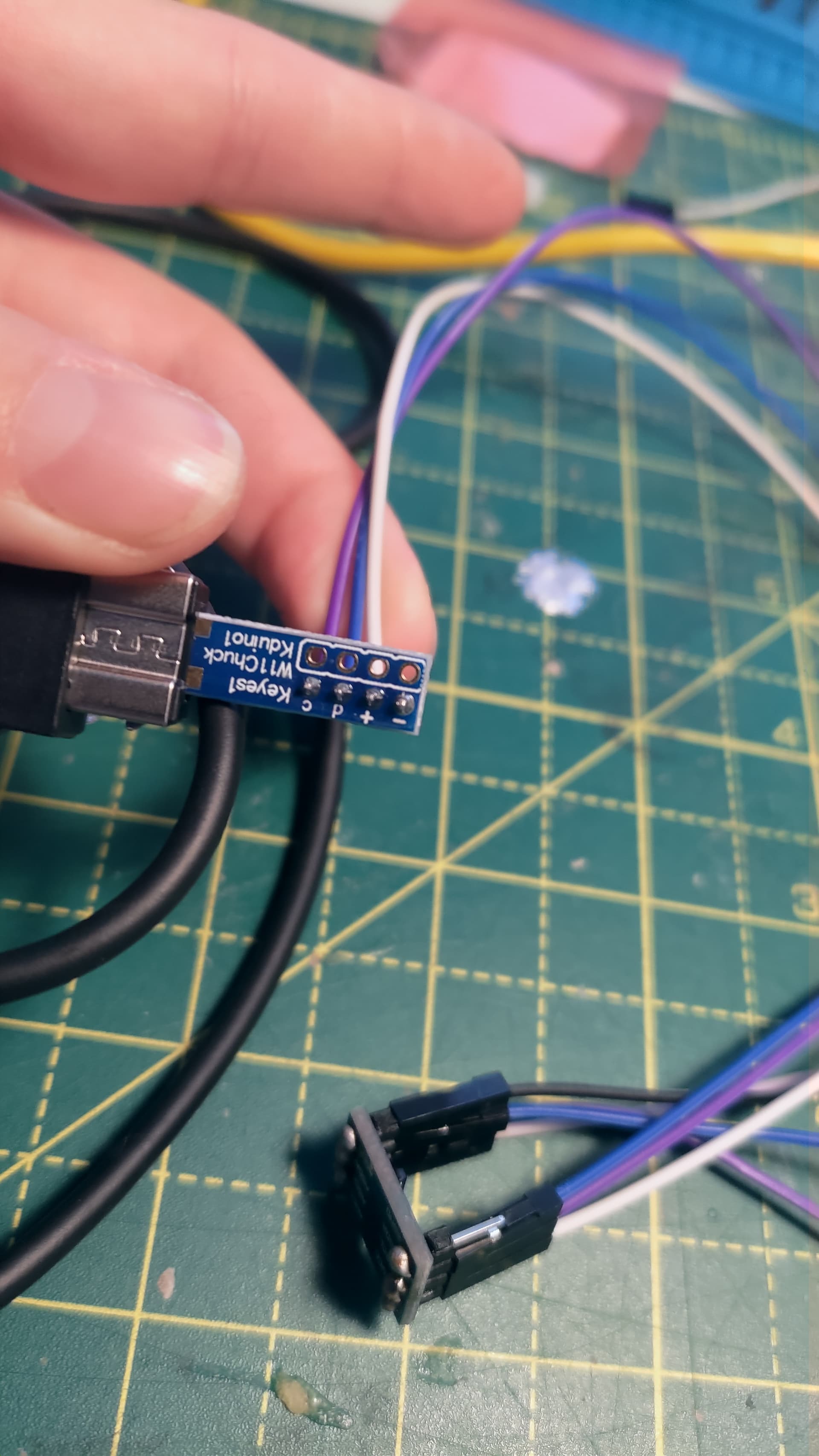
If that's true, you didn't connect it properly:

The power and ground wires should be on the outer pins and the I²C lines on the inner pins.

I've gotten home and tried to wire it again, triple checking that my wires are in the right place, but still no luck. I also tried with and without a ground wire back to the Arduino, and just in case, the ground wire between the shifter and nunchuk. I've taken photos of my wiring for the version where neither ground is connected. White is 5V, Black is ground, Blue is data and Purple is Clock. As I'm having so many issues I'm going to try and problem solve with the sparkfun board, as that at least came back with data even if it was wrong.
EDIT: I am no longer using this blue level shifter as I couldn't figure out what was wrong. I am now looking to use the SparkFun level shifter instead, as discussed below


Hi,
Do you have a DMM?
If so can you please check that 3V3 is getting to the nunchuck?
The PCB is connected into the socket the right way around?
Pictures tell a story and unfortunately Fritzy images don't.
Can you please reverse engineer and draw your circuit on paper and post an image?
Include component names and pin labels and power supplies.
If you look at your Fritzy it has no pin names for that level changer, so how were we to know it had a 5V to 3V3 regulator on it, the nunchuck pcb has its pin names obstructed.
Thanks.. Tom.. ![]()
![]()
![]()
![]()
1 Like
Hi Tom, I've got one on the way but it won't be here now until mid next week. By PCB and socket, do you mean if the pins I've soldered in are the right way around? It was a second attempt at soldering the board as I accidently damaged the first one with too much solder, so I flipped the board to avoid making the same mistake.
I can just use the sparkfun board level shifter instead, but the data is coming back wrong at the moment, just trying to troubleshoot why if I don't have the tools to fix the smaller board in the diagram. I'll get onto that drawn version in case it helps at all