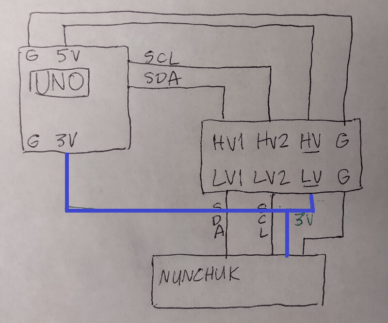
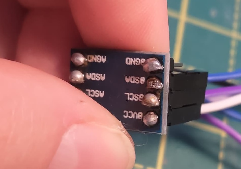
I've made a new diagram for just this part of the circuit, all I'm looking to solve right now is being able to accurately print the slave data to the monitor. As the smaller blue board was giving me so much trouble, I'm just going to use the sparkfun board. In case my soldering job caused the issue, I've ordered a second clean board that I'll get some help with attaching the pins next week
I'm using the following code to read the nunchuk data and print it to the monitor, taken from the website in the code . All I want to do is read it correctly at the moment:
/*
 * ArduinoNunchukDemo.ino
 *
 * Copyright 2011-2013 Gabriel Bianconi, http://www.gabrielbianconi.com/
 *
 * Project URL: http://www.gabrielbianconi.com/projects/arduinonunchuk/
 *
 */

#include <Wire.h>
#include <ArduinoNunchuk.h>

#define BAUDRATE 19200

ArduinoNunchuk nunchuk = ArduinoNunchuk();

void setup()
{
  Serial.begin(BAUDRATE);
  nunchuk.init();
}

void loop()
{

  nunchuk.update();

  Serial.print(nunchuk.analogX, DEC);
  Serial.print(' ');
  Serial.print(nunchuk.analogY, DEC);
  Serial.print(' ');
  Serial.print(nunchuk.zButton, DEC);
  Serial.print(' ');
  Serial.println(nunchuk.cButton, DEC);
  Serial.print(' ');
  delay(250);
}
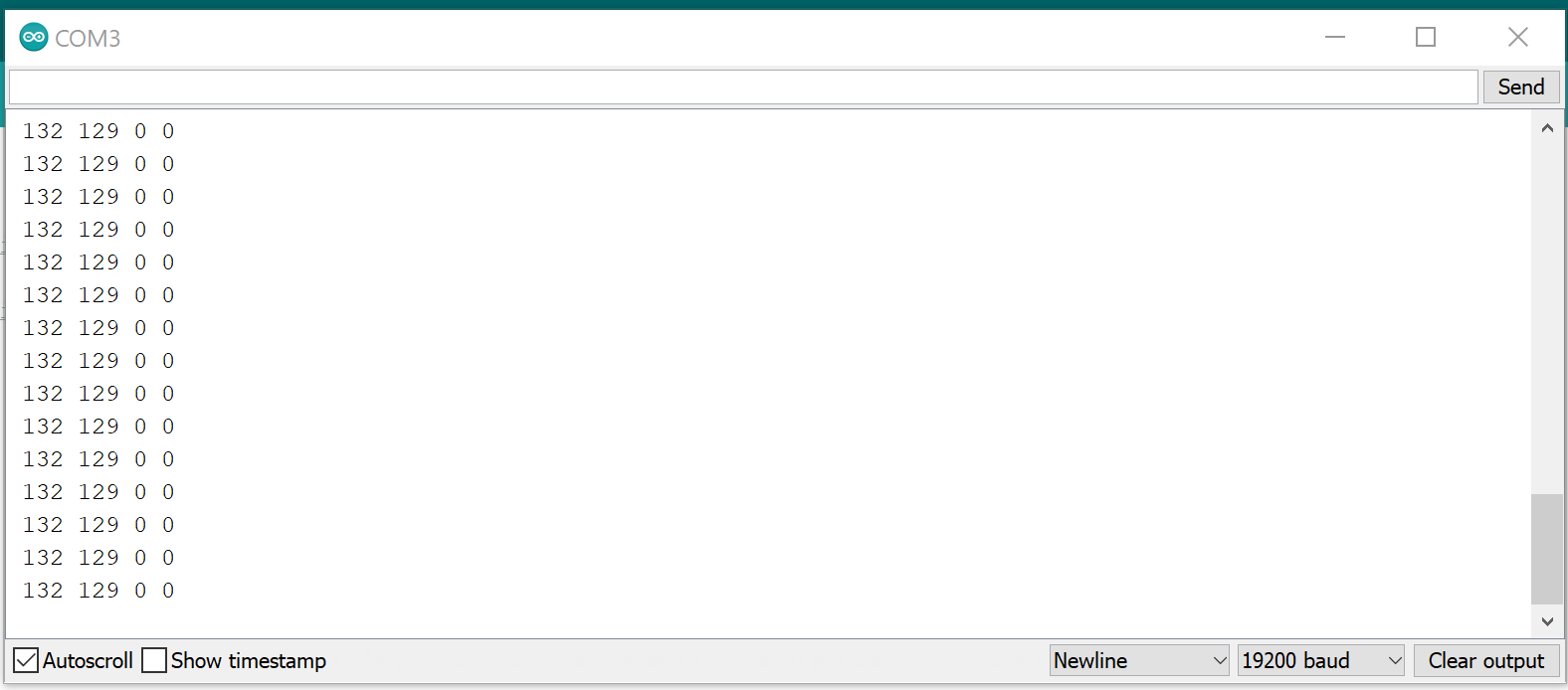
When I run this code on just the 3.3v pin with no level shifter, I get this data back in the board, and it accurately updates when I move the joystick or buttons. This is exactly the data I want
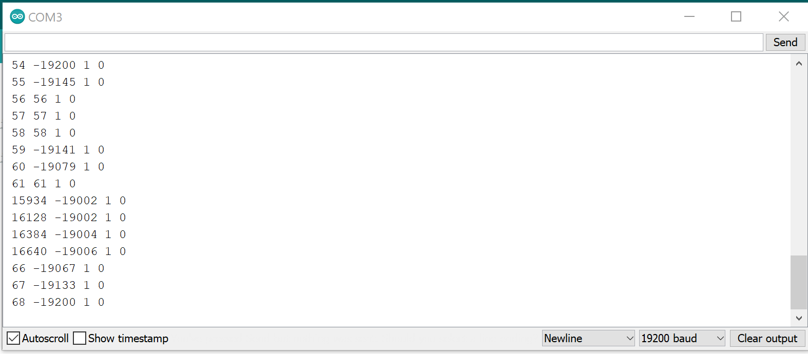
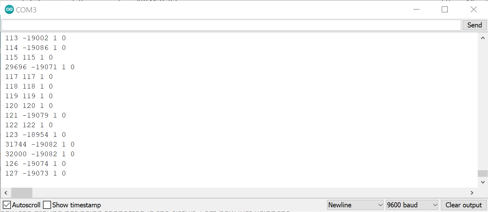
Then, when I use the 5v pin and the shifter, I get this data back. I don't feel like the data is random as it goes between the same numbers.
The rest of my circuit uses 5v. That's why I was asking if I could use both 5V and 3.3v pins, as if that worked, it would bypass the need for a shifter and I wouldn't be dealing with any issues 
@dlloyd Thanks for the pull up suggestion, but there will be 2 i2c devices eventually in this circuit, I'm just not worrying about the second for now as it is working and connecting fine.
@TomGeorge By one on the way I meant the DMM sorry.
@krishna_agarwal Thanks for answering the initial question, my two posts got merged and I lost a lot of replies about this different question. I was planning to use them in my uni write up of this project and having proof is very helpful 
@Paul_B The photos are wired in that way per the suggestion of the thread. As the schematics for the board strangely show the ground not being connected in the circuit. I am now just using the sparkfun board instead as its being more responsive, the problem is now that the values it reads are wrong.