I'm a beginner with these types of projects. I'm building musical jewelry boxes for my daughters using an Uno board with a wave shield attached. So far everything has gone pretty smoothly and the shield is playing the music nicely. Now I'm just trying to attach a snap action switch to the board so that the music stops playing when the lid to the jewelry box is closed. I cannot find any guidance though as to where to solder the wires from the switch onto the board. If anyone could help, I'd be super appreciative. Thanks in advance.
Tell more: What kind of Arduino? Is it a clone? Is the device powered by a battery? Does it make an unpleasant noise if you kill power while it's playing?
We just need to know what this snap action switch is.
Can you post a picture of it or better yet post a link to where you got it from.
I used a Hall effect switch and a pair of magnets in something similar I made.
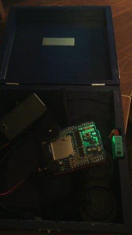
The Uno shield is the one that uses the battery. There's no funny noise when I turn the power off. I'll include a pic of the project. I got the snap action switches from Amazon here: http://www.amazon.com/gp/product/B00H8TZ5TW?ref_=oh_aui_i_sh_post_o40_img&ref_=redir_mobile_desktop
That dice game is pretty cool. There is so much that can be done with these circuit boards. I started specifically to make these music boxes for my girls but it may become a hobby now.
Here is a picture of where the project is at this point.
On the snap action switch, I have a lead coming from the "Normal Open post" and one from the "Com" post. When I built the boxes the first time, I used a dollar store MP3 player and soldered one lead to the lithium battery and one the the MP3 player board. It didn't take long for the dollar store MP3 player to quit though so now I'm trying to make them tough so they last. Now I just don't know where to put the leads on the wave shield/Uno board or if I have to include any code.
Well despite what that page said these are not called "snap action switches" by the rest of the world, they are called "micro switches".
Connect com to ground and either of the other connections to an Arduino input. Then enable the internal pull up resistors in the setup function of your code with the pinMode call.
Then in the code you simple read the state of the switch with a digitalRead call. This will read HIGH or LOW when the switch is open or closed. Choosing the other switch connector will invert this HIGH and LOW.
For inputs see this:-
http://www.thebox.myzen.co.uk/Tutorial/Inputs.html
Is there some reason why the switch wouldn't just open the battery circuit?