This is my first project. I'm using an Arduino due to play a 200 ms long sound upon receiving one of two pulses: Pulse 1 triggers 200 ms of white noise, Pulse 2 triggers 200 ms of a pulse wave. I'm using the due's built-in ADC to generate the sounds. The issue: Before playing any sound, the output is quiet. However, after playing a sound for the first time, in the baseline period when receiving no trigger pulse, I hear an unwanted noise different from my (coded) generated white noise. I assume it's due to the voltage at the ADC fluctuating? How do I get rid of this? Pull-down the ADC output pin? If yes, how do I do that?
Thanks in advance, I greatly appreciate your help!
The code:
#include <GPIO.h>
unsigned short amplitude = 255; // 0 to 255 (PWM)
unsigned short amplitudeTone = round(amplitude*0.3);
unsigned short restingVoltage = 0; // Not sure if needed
unsigned long samplingFreq = 100000; // sampling frequency in samples/second
unsigned long toneFreq = 5000; // Frequency of pulse wave
int delaytimeNoise = round(1000000/samplingFreq) - 7; // delay in us between samples. Have to subtract the time it takes for the code to execute (7 us)
int delaytimeTone = round(1000000/(toneFreq*2)) - 7; // delay in us between samples. Have to subtract the time it takes for the code to execute (7 us)
int playSoundFor = 200; // time that the sound is played in ms
int pulseWhiteNoise = 0; // to read state of trigger pin. If 1, pulse is coming in
int pulseTone = 0; // to read state of trigger pin. If 1, pulse is coming in
int count = 0; // used to only execute the loop as long as it takes to reach playSoundFor
int maxcountNoise = samplingFreq / (1000/playSoundFor);
int maxcountTone = toneFreq / (1000/playSoundFor);
bool playWhiteNoise = false; // used to switch betweend pulse detection and sound playing
bool playTone = false; // used to switch betweend pulse detection and sound playing


GPIO<BOARD::D52> noise_in; // PIN 52 is first input pin
GPIO<BOARD::D51> tone_in; // PIN 51 is second input pin


void setup() {
  analogWriteResolution(12); // 12 Bit
  pinMode(DAC0, OUTPUT); // Define DAC0 as output pin
  noise_in.input(); // set first input pin as input
  tone_in.input(); // set second input pin as input
}

void loop() {
  if (playWhiteNoise) { // code that plays white noise
    if (count <= maxcountNoise) {
      int voltage = random(0,amplitude); // random PWM to feed to the DAC
      analogWrite(DAC0, voltage); // takes approx. 7 us
      count++;
      delayMicroseconds(delaytimeNoise); // wait until playing next sample
    }
    else {
      playWhiteNoise = false; // stop playing sound if max time is reached
      count = 0; // reset counter
      //analogWrite(DAC0, restingVoltage); // not sure if needed?
    }
  }
  else if (playTone){ // code that plays a square pulse
    int voltage = amplitudeTone; // lower the volume (square pulse is harsh)
    if (count <= maxcountTone){
      analogWrite(DAC0,voltage);
      delayMicroseconds(delaytimeTone); // This delay time is calculated to generate the requested frequency
      voltage = 0;
      analogWrite(DAC0,voltage);
      delayMicroseconds(delaytimeTone);
      count++;
    }
    else {
      playTone = false; // stop playing sound if max time is reached
      count = 0; // reset counter
      //analogWrite(DAC0, restingVoltage); // not sure if needed?
    }
  }
  else {
    pulseWhiteNoise = noise_in;
    pulseTone = tone_in;
    if (pulseWhiteNoise == HIGH){
      playWhiteNoise = true; // play white noise on input
      int voltage = random(0,amplitude); // random PWM to feed to the DAC
      analogWrite(DAC0, voltage); // takes 7 us
      count++;
      delayMicroseconds(delaytimeNoise); // wait until playing next sample
    }
    if (pulseTone == HIGH){
      playTone = true;
    }
  }


}
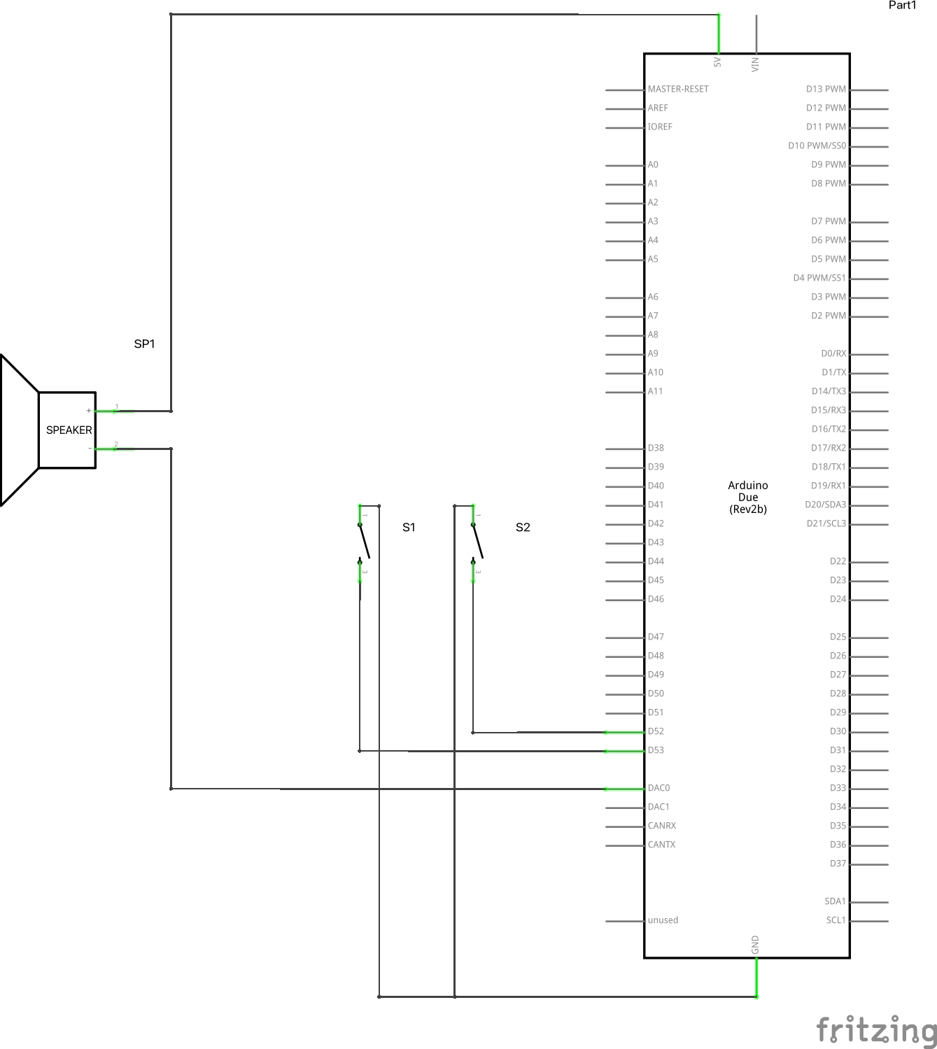
I wasn't sure how to depict the inputs. They're not actually switches, they provide digital inputs. The speaker here really is an amp going to a speaker.
Alright, drawing the schematic will take me a bit. I power it from a 12V power supply. But if that was the issue, there would also be noise before playing a sound for the first time, wouldn't it?
Think about the time helpers would need producing useless guesses that You need to evaluate. Schematics is an investment even for You. Some day You might want to make a change or use this project as a starting point for new adventures. You will not remember the details for ever.
do you have an oscilloscope to look at the output signal
e.g. this is using a DUE to output sine waves on DAC0 and DAC1
Thanks for the suggestion. I have access to an oscilloscope, but it'll take some setting up. The sound is not distorted though. Both the white noise as well as the pulse wave sound like they're supposed to. Measuring the output with an oscilloscope during the baseline will probably just tell me that there's noise.
Maybe I'm missing something, but the use of "delaytimeNoise" looks odd both in the calculation of the value and the fact that it's cast as a signed integer where delayMicroseconds wants an unsigned integer as its argument.
Maybe I'm missing something, but the use of "delaytimeNoise" looks odd both in the calculation of the value and the fact that it's cast as a signed integer where delayMicroseconds wants an unsigned integer as its argument.
Hmm okay declaring it as an unsigned int will be an easy fix. What do you mean by "odd"? Did I use wrong syntax? That part of the code seems to work.
I saw Your reply but felt like encoring You anyway, just to be sure...
You did so successfully!
I added a schematic. Moreover, while doing so I realised that I might have wired the speaker incorrectly. It should probably go to ground, not to 5V, am I right?
I see no schematics. Where did You post it? Posting in the last reply is prefered.
You need a capacitor in serie with the speaker, else it might get damaged. Then GND or posive is no big difference I think. Use GND.
Found it. The most appreciated is posting it as a picture. Downloading is not popular. It fills up helpers equipment...
Being coockied is no, no here... Picture please.
You will eventually burn out the output pin by driving a speaker directly, and possibly destroy the Due as well. Use an audio amplifier to drive the speaker.
I see no schematics. Where did You post it? Posting in the last reply is prefered.
You need a capacitor in serie with the speaker, else it might get damaged. Then GND or posive is no big difference I think. Use GND.
Found it. The most appreciated is posting it as a picture. Downloading is not popular. It fills up helpers equipment...
Being coockied is no, no here... Picture please.
Wow, that seems like an awfully negative way of seeing it. Why do you think I can't be bothered to provide accurate details? Do you instead mean that I did not provide accurate details initially (because I didn't know better), then apologised and provided the details you were asking for? As I said, I greatly appreciate your help, but that statement doesn't seem to be very productive.
Explaining my statement about the DAC output wiring: I was asking if the output is wired up correctly like that or whether I should connect the positive pin of the amp to GND as opposed to 5V on the Arduino side. As I explained in my first post, I'm worried that the voltage at the DAC output is fluctuating, and now I was asking if connecting it to GND might prevent that. Railroader suggested to try that.
Yes, thank you! I'll try it first thing in the morning (it's evening where I'm at and I don't have access to my experimental rig where the Arduino is).
Noise is often a problem with electronics, especially abused electronics. Like, for example, connecting the output of an amplifier to the positive terminal of a power supply.
For help with your problem, post a complete, accurate schematic diagram of your setup, with links to the components, such as the mysterious amplifier.