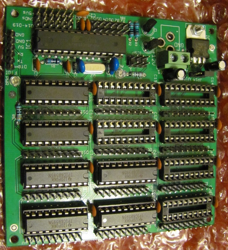
i am building a large led Gps controlled clock, a friend is helping me with code and i have bought a 12 digit driver board from ( crossroads ) i am only using 6 of the digits. anyway we are having a problem to get the GPS to communicate with the board.
the GPS is a Ublox 6 and i have gotten it to work fine with a FTDI to USB on my laptop.
i am guessing i need to use a converter of some sort to make it communicate with the board,
the processor on the board is the same as used on the UNO.
attached is a copy of our code, can anyone give it a look over and tell me is you see any obvious problems ? let me know if you need any additional info as well.
thanks.
If that's it, then you will hook the board 5V to ublox Vcc and GND to GND. However, the ublox TX and RX are 3.3V signals, not 5V signals like the ATmega328 pins 2 and 3 (DG2 and DG3 on the board).
I always use level converters for data signals like this. They're cheap and efficient, and they are required when the speed is higher than typical Serial baud rates.
Some people recommend just using a few resistors for your case:
For connecting the board DG2 (TXpin) to the ublox RX, use a resistor divider to scale the 0.4V-to-4.7V signal down to 0.25V-to-3V or so. Almost any pair of resistors in a ratio 1:2, and that add to 3K to 60K will work. For example, a 10K and a 22K would be fine.
For connecting the board DG3 (RXpin) to the ublox TX, use a pullup resistor of 4.7K to 10k.
Cheers,
/dev
P.S. DG2 and DG3 are from the schematic. They are screenprinted on the board as D2 and D3.
i think we may have it figured out..they guy that is helping me with code is good with code, but good with electronics, so we have to work hand in hand.