Hello all. I have a project for which I have been using the Arduino Nano Every as a daughterboard but I am now integrating the Every into the schematic for the main board. I noticed something strange about the USB port in the Nano Every schematic and I was wondering if anyone here could shine some light on it.
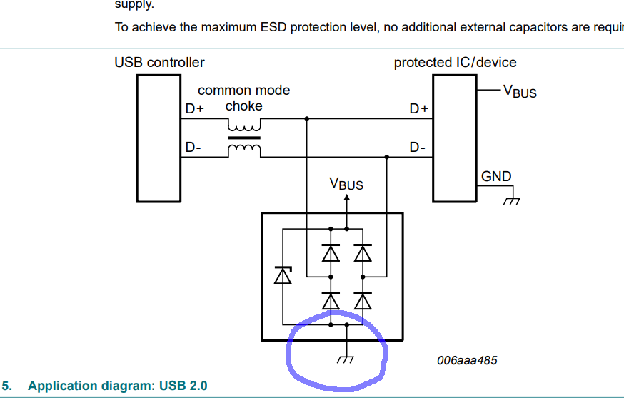
Compared to the arduino nano there is some extra passive circuitry that appears to do some over voltage/ anti static protection. The weird thing about this is that I am seeing something that I have not seen before: the USB shield/ housing is connected to an RC circuit that is then connected to ground instead of directly to ground. This node is also shared with the pin on the schottkey diode network that I would normally expect to be connected directly to ground. In fact, the data sheet for the schottkey network (PRTR5V: https://www.mouser.com/datasheet/2/916/PRTR5V0U2X-2938759.pdf) shows this pin connected directly to ground as well.
I realize that I can just connect a 0 ohm resistor instead of the 1M resistor if this section of the schematic ends up giving me trouble down the road. However I wanted to see if anyone here could help me explain why this section was done the way that it was before I just copy it. I have screenshots of the schematic with the section in question circled below.

Thank you for your time.