I'm looking for a TLL / FTDI board, whatever these are called, to convert USB to VCC,GND,TX,RX pins. I need the VCC to be 5V and TX/RX 3.3V. Something like this, but ideally in a form factor like this.
The breakout board linked above, and many other I found online, can be switched between 5V and 3.3V, by changing the voltage of VCC and TX/RX pins together. I need something with 5V power and 3.3V IO.
Do you know where I can find such a board ?
Adaptor based on CP2102 like this one?
That looks fine, having both 5V and 3.3V VCC's, but are the TX and RX lines definitely 3.3V ?
cpper:
That looks fine, having both 5V and 3.3V VCC's, but are the TX and RX lines definitely 3.3V ?
You might think so, but in fact that module (I have several like that) produces about 4.3V on the "3.3V" output and on all the I/O pins. Why, you ask? Well the CP2102 is exclusively a 3.3V part. However, probably to make it more useful with 5V Arduinos, the designer hacked it so everything is one diode drop below the USB 5V level. This works fine with 5V Arduinos, and will probably work fine with 3.3V Arduinos like the Pro Mini 3.3V 8 MHz. The Atmega 328P will work to 5.6V even if fused at 8 MHz. But using this module with any device that isn't 5V tolerant could destroy the device because 4.3V probably exceeds the device's absolute maximum rating.
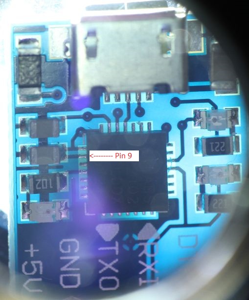
The hack consists of connecting the reset pin (pin 9) to the USB 5V source. That causes everything to operate through the protection diode on the reset pin. Hence the one diode drop. I'll attach a picture showing where pin 9 is, and the trace running from it. The item referenced by PaulRB also appears to have that trace, assuming the Ebay picture is accurate. If reset is not connected to anything, you will get 3.3V output on everything except the 5V pin, which is actually just the USB 5V power.
I don't know of a current source of these modules without the trace to pin 9. But you can always just cut it. Carefully.
But I'm curious why you need 5V power and 3.3V I/O.
Edit: Here's a video on cutting that trace to get 3.3V I/O back (however, I just use a knife):

Thanks for the info, Sherman. I found the CP2102 at local stores here and here. The trace you mentioned is visible in the product pics on both sites.
After some more looking around, it seems products LC231X and LC234X from FTDI would also solve my task.
My goal is to connect a GPS module with 5V power input and 3.3V TX/RX to a computer USB port.
ShermanP:
You might think so, but in fact that module (I have several like that) produces about 4.3V on the "3.3V" output and on all the I/O pins.
I'll have to take a look at the ones I have, but the CP2102 has a built in voltage regulator for 3.3 +/-0.3V @ up to 100 mA. If it's putting out 4.3V it's way out of spec. I've used them with 3.3V processors and never had an obvious issue.
I'd assumed the way these modules work is that the 5 V output is directly from the USB port and the 3.3 V out and the signal lines are based on the CP2102 internal regulator.

cpper:
The CP2102 board has arrived. The mentioned trace seems to not be present:
You should be able to simply plug the board into a USB port and measure the voltage on TXD with a voltmeter. If it's 3.3V +/-0.3V as I expect per the CP210x datasheet then you should be good to go.
Yes, that one should work fine. I just wish we had an Ebay seller that reliably provided that version. The seller I found a couple years ago no longer sells the item at all. And the last time I tried, Banggood sent me the bad version, but that's been over a year ago. But it always seems to be the bad version that's shown in listing pictures, as was the case this time, so you can't go by that.
Other differences I've noticed between good and bad versions: Good ones have what I think is a fuse (marked "4" in the picture) next to the USB connector, instead of a jumper. Good ones say TXD, whereas bad ones say TXO.
Just tested a couple of my cp2102 adaptor boards:
| Pin | #1 | #2 |
|---|---|---|
| Power Led | Green | Red |
| 5V | 4.99V | 4.99V |
| 3V3 | 3.53V | 3.18V |
| DTR, RXI, TXO | 3.53V | 3.18V |
I guess they're both within the 3.3+/-0.3V spec. So no RESET pin hack?
Both have pins labelled TXO not TXD.
Piqued my curiosity. Give me a few weeks and I will have an opinion! ![]()
PaulRB:
Both have pins labelled TXO not TXD.
Well so much for my rules of thumb. I think both of those are fine.