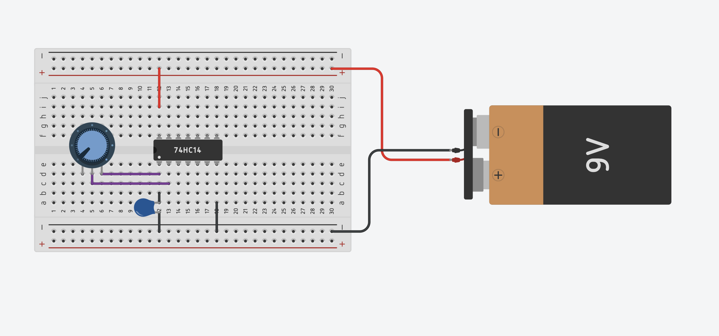
I am trying to combine two projects. I want to replace the resistor/potentiometer in an existing project with an Arduino that should produce variable resistance. I'll explain:
1.) I have a project without an Arduino: It is an oscillator producing a pitch. The oscilator uses a chip (see below). Between leg one (in) and two (out) of the chip is a resistor. I can use a 100K resistor for a stable pitch or use a 10K potentiometer and control the pitch to make it higher or lower.
2.) I have another project with an Arduino. It uses a super straightforward 'capacitive touch' code and a buzzer. When the sensor reading of the capacitive touch pin goes up, the buzzer Hertz goes up. When the value goes down, the buzzer tone goes down.
What I would like to do is connect pin 1 and 2 of the chip (project 1) to the Arduino (project 2), and then have it function as a sort of variable resistor, controlling the resistor value with the capacitive touch sensor. So instead of buzzing the piezo buzzer of project 2, I want the pitch of project 1 to go up or down based on the capacitive touch reading.
I am not sure if this is at all possible. I am also not an expert in both general electronics and in Arduino programming, so I am kind of clueless where to start looking. Whatever I search for in examples, gives me projects where an Arduino is combined with a resistor or potentiometer. Not where it replaces them.
If there is anyone that has ideas on how to proceed, I'd be grateful!
For those who want to know, project 1 is the Oscillator from Nicola Collins' book on Handmade Electronic Music, using a CMOS Hex Schmitt Trigger Inverter Integrated Circuit (I used a CD40106).
As @jremington told you you could use a digital potentiometer. However, the quoted AD5171 is for up to 5 volts and the CD40106 is for up to 15 volts. How many volts does your circuit run at? If it is more than 5 volts you will need to see if there is a suitable high voltage digital potentiometer.
This will most probably generate a simple square wave. Every Arduino can generate square waves of various pitch, see e.g. tone()/noTone() in the Arduino Reference.
Main puzzle for me seems to be, how to integrate this in my circuit where my current analog potentiometer is (so between a point X and a point Y). In the tutorial that the link shows, it only goes from the digital potentiometer to a LED. So one link, between the Arduino (5V) and the LED. In my circuit, the potentiometer connects two pins from the CD40106..
Any circuit connected to the Arduino I/O pins must operate on voltages between 0 and 5V or 0 and 3.3V, depending on the Arduino model.
If you are using a 9V battery to power the Arduino, a built-in voltage regulator converts that to the appropriate voltage, which the rest of your circuit would normally use.
Can you please post a copy of your circuit, a picture of a hand drawn circuit in jpg, png?
Hand drawn and photographed is perfectly acceptable.
Please include ALL hardware, power supplies, component names and pin labels.
Sorry people, hoped the idea was clear. The picture is from the book I am using (by Nicolas Collins). The simplified drawing is one I made in tinkercad. So where the potentiometer is, I would like there to be maybe this digital potentiometer, that is controled by an Arduino (using capacitive touch but it could have been any other thing, as long as it works as a potentiometer and has two legs that can go in the two spots where now the analog potentiometer goes.
Does this make any sense? If you say it can't be done, please let me know as well!
Thanks for your patience
As already recommended, use the Arduino tone() function instead of that circuit. That would require adding or changing just one or two lines in the "capacitive touch" project code.
You could still use the variable resistor to change the tone, by reading its value with an analog input.
Ok thanks. I really want to continue with the handmade electronics, but if I understand correctly, the Arduino cannot be added as a variable resistor in this circuit, so I'll skip that idea. I'll use the capacitive touch for other projects instead of combining it with this one.
If you would have an alternative oscillator scheme with the resistor connected to ground, you could simply replace the resistor with a mosfet. The mosfet could then be controlled by arduino (pwm with low pass filter).
I am sure such schemes exist, but maybe not with an inverting schmidt trigger...
Maybe simply google "schematic oscillator inverting schmidt trigger" and see what you find.
 I just really like my oscillator project and all the electronic add-ons I wille be making.