Use esp32 how to working tft lcd with spi

JWS0392-B4042(MCUSPI) (4).pdf (1.3 MB)
SPI 접선도 (4).pdf (348.1 KB)

i want to working this lcd how to upload bmp file?
this lcd use st7796 driver
i dont know how to conect wire and use library
can i use with out library?
please help....
no matter arduiono-uno or esp32

First off. Arduino Uno has 5V logic. If you want to use a 2.8V display you need level-shifters on every logic pin.

The ESP32 has 3.3V logic. You can connect the 3.3V logic pins directly to the ST7796S display.

I suggest that you install TFT_eSPI library via the IDE Library Manager.
Select Setup27 but edit it e.g. comment the define

// Display type -  only define if RPi display
// #define RPI_DISPLAY_TYPE

I strongly advise starting with displays that come with a pcb and 2.54mm header pins.
Raw displays with a 40-way ribbon are difficult to connect.

If you have any problems, quote the "User Setup" and show a photo of your actual wiring.

Once you have everything working with the ready-made display pcb you can try with a custom ribbon connector and custom pcb.

David.


i use this adapter
can i use this lcd without extra cuircit??

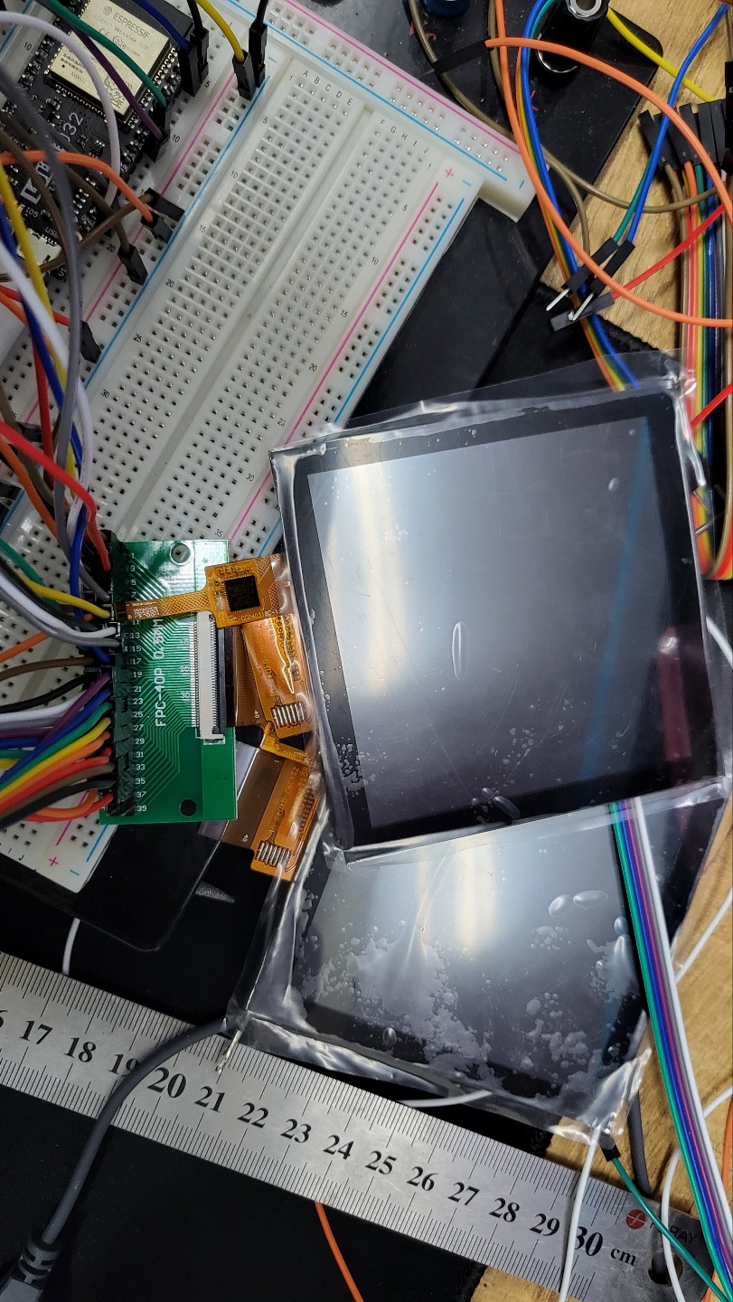
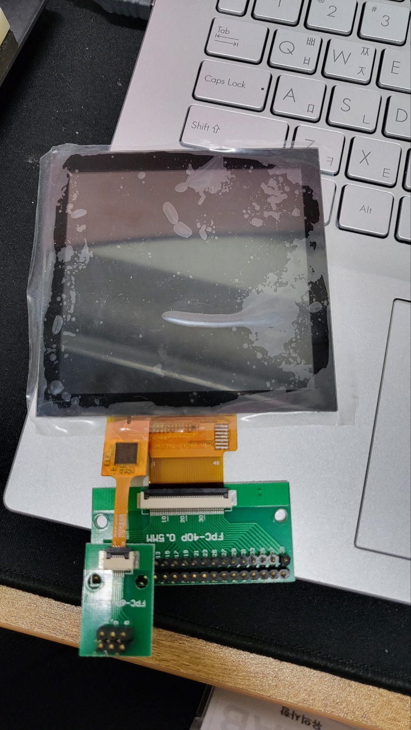
Yes. Your interface connections look correct. Your ZIF ribbon adapter looks correct.

But you still have to connect the correct signal to the Pico ESP32.

Do you have any experience of using ST7735, ILI9341, ... TFT controllers ?
The ST7796S is very similar. However the TFT_eSPI library should look after the low level differences.

David.

Sorry, I don't have experience using other lcd
So very diffucult use this lcd.... i dont know wiring and using library...
I know i need to study
Can you show me wiring and code for that lcd???

Sorry to make bother you but i really need.....
What pin can i use in that pin map for library
I cant match wire...

I suggest that you buy any SPI OLED, TFT, ... that comes on a pcb. Just to gain experience in connecting to the ESP32. And using the appropriate library.

If you are unsure of your ESP32, post a link to the actual ESP32 board that you have bought.

Seriously. Your ribbon connections for 4-wire SPI look correct. You just have to wire GND, 3.3V, and the appropriate GPIO pins.

If you did not write the wiring PDF yourself please give us some idea of your experience. e.g. blinking LEDs, ADC, writing to Serial, ...

David.

Thanks david
Can you tell me what pin conect esp32 for working lcd using library

On this pin map

Like this

http://naver.me/I5ovhdjL
Use this lolin esp32

Connect the LOLIN pins to the ribbon pins.

//            LOLIN     RIBBON
#define TFT_MISO 19   //16 SDO
#define TFT_MOSI 23   //17 SDA
#define TFT_SCLK 18   //10 WR Serial Clock
#define TFT_CS   15   // 8 CS Chip select control pin
#define TFT_DC    2   // 9 RS Data Command control pin
#define TFT_RST   4   // 7 RESET Reset pin (could connect to RST pin)

connect LEDK to GND
connect LEDA to 3.3V via a 39R resistor

Seriously. It is much safer to use a display with ready-made pcb and pin header like the connection diagram.

You have not explained your experience with electronics.
Arduino users connect modules with numbered pins.
Electronics professionals need to understand what they are doing with


i tried like this but lcd powers not on


wiring refer to this file

//            LOLIN     RIBBON
#define TFT_MISO 19   //16 SDO
#define TFT_MOSI 23   //17 SDA
#define TFT_SCLK 18   //10 WR Serial Clock
#define TFT_CS   15   // 8 CS Chip select control pin
#define TFT_DC    2   // 9 RS Data Command control pin

and flow like this and changed initial code

Are you taking the p*ss?

No self-respecting rat would expect that mess to work.

Buy a proper SPI pcb.
Connect the nine wires to your ESP32. Document the wire colour for each signal.
Run the TFT_eSPI examples.

It should work first time !!

David.

in the default setup files of the bodmer lib the lines
#define TFT_BL 26
#define TFT_BACKLIGHT_ON HIGH

were missing for my display (hailege, 2,8 tft, spi, il9431, https://www.amazon.de/-/en/gp/product/B07YTWRZGR/ref=ppx_yo_dt_b_asin_title_o04_s00?ie=UTF8&psc=1). so it might just be that the led backlight isnt being turned on. but of course the tip might not help with the st7796s.

i used this esp 32: https://www.amazon.de/-/en/gp/product/B071P98VTG/ref=ppx_yo_dt_b_asin_title_o05_s00?ie=UTF8&psc=1

edited because the display was actually not az delivery but hailege.

here my working user setup (basically #42 with additional lines)
the links from gpio to the tft-board pins are basically self explanatory

// See SetupX_Template.h for all options available
#define USER_SETUP_ID 42

#define ILI9341_DRIVER
#define TFT_BACKLIGHT_ON HIGH

#define TFT_MISO 19 
#define TFT_MOSI 23
#define TFT_SCLK 18 // (SCK)
#define TFT_CS   15  // Chip select control pin
#define TFT_DC    2  // Data Command control pin
#define TFT_RST   4  // Reset pin (could connect to RST pin)
#define TFT_BL 26 // LED


// Optional touch screen chip select
//#define TOUCH_CS 5 // Chip select pin (T_CS) of touch screen

#define LOAD_GLCD    // Font 1. Original Adafruit 8 pixel font needs ~1820 bytes in FLASH
#define LOAD_FONT2   // Font 2. Small 16 pixel high font, needs ~3534 bytes in FLASH, 96 characters
#define LOAD_FONT4   // Font 4. Medium 26 pixel high font, needs ~5848 bytes in FLASH, 96 characters
#define LOAD_FONT6   // Font 6. Large 48 pixel font, needs ~2666 bytes in FLASH, only characters 1234567890:-.apm
#define LOAD_FONT7   // Font 7. 7 segment 48 pixel font, needs ~2438 bytes in FLASH, only characters 1234567890:.
#define LOAD_FONT8   // Font 8. Large 75 pixel font needs ~3256 bytes in FLASH, only characters 1234567890:-.
#define LOAD_GFXFF   // FreeFonts. Include access to the 48 Adafruit_GFX free fonts FF1 to FF48 and custom fonts

#define SMOOTH_FONT

// TFT SPI clock frequency
// #define SPI_FREQUENCY  20000000
// #define SPI_FREQUENCY  27000000
#define SPI_FREQUENCY  40000000
// #define SPI_FREQUENCY  80000000

// Optional reduced SPI frequency for reading TFT
#define SPI_READ_FREQUENCY  16000000

// SPI clock frequency for touch controller
#define SPI_TOUCH_FREQUENCY  2500000

Please post a link to the actual display that you have bought.
Copy-Paste the link so that there are no spelling mistakes.

Yes, we can help you (and other readers) with the Bodmer Setup files.
But only when we can identify exactly which screen you have on your desk.

Regarding the photos in #11. No human can decipher the wiring.
But if the wires were spread neatly it would make all the difference.
i.e. if you could see which colour wire goes to which pin on the ESP32.
i.e. if you could see which colour wire goes to which pin on the TFT pcb.

David.

Thanks for the links. It looks like a regular Red ILI9341 SPI display and a regular ESP32 board.

So I would look at the "nearest" User_Setup e.g. Setup42_ILI9341_ESP32.h
And simply copy the wiring.

Then select Setup42 in the User_Setup_Select.h

Looking at the pcb photo in your link. i1 looks like a 3.3V regulator. And there is no Q1 transistor to switch the LED backlight.

Simple enough. Read the part number on the U2 / i1 chip.

Apply 3.3V to the LED pin via a 1k0 series resistor. A transistor will switch on the LED.
If there is no transistor you need to reduce the resistance value to 4R7 .. 33R to light the LED.

If there is no transistor you can't control the LED in software. Just hard-wire with a small resistor.

Incidentally, Red SPI displays have been appearing with ST7789 controllers.
And you must always compare your pcb with the photo on the sale link.
Your pcb might have a real U2 and Q1 !!

David.

1 Like

This topic was automatically closed 180 days after the last reply. New replies are no longer allowed.