i want to isolate a 115200bps UART between 2 arduino nanos. The only optocouplers i have are PC817C. I dont know what to look for in the datasheet to see if they are compatible.
Would the pc817c work for my application?
i want to isolate a 115200bps UART between 2 arduino nanos. The only optocouplers i have are PC817C. I dont know what to look for in the datasheet to see if they are compatible.
Would the pc817c work for my application?
Could you give a link to the datasheet that you are looking at ?
Look for the maximum frequency or try to find a graph. Here are frequency responses of two datasheets for the PC817C:


I think they are too slow.
Whats the easiest way to isolate this uart signal. Is there a breakout board i can buy on amazon that i can just drop in the circuit? i did a quick search but i must be looking for the wrong thing. not much comes up when i search for arduino uart isolator.
All my search results just come back with usb to uart converters
Searching for: digital isolator
This "magnetic" isolator pops up (I don't know what it is).
The first page in this datasheet for the **ADUM1201ARZ ** explains some things im pretty sure with optocouplers you get 100% galvanic isolation? the item you shared looks pretty interesting.
https://www.mouser.com/datasheet/2/609/ADuM1200_1201-1503479.pdf
6N137's are popular high-speed optocoupler's that I've used for 2-way UART communication. 115200bps worked without issue.
From memory, I think I got them working by following this schematic: serial from Mega powering Nano - #9 by kpg
It might if you use a 1K current limiting resistor.
Have any of you ever used a magnetic isolator/ADUM1201? Would that provide the same isolation as optocouplers? Im thinking about getting some optocouplers and the magnetic isolator just to mess around with.
I want to make sure there is no ohmic connection between the uart's.
The ISO6721 General-purpose, dual-channel, 1/1 digital isolator looks like a possible solution.
Mouser might be you best bet to get some soon.
haven't used 1201, but this looks like a good example using serial line.
I guess the obvious question is why so high a baud rate ? If it was 9600 it would be far easier .
Why do you need isolation ?
It always helps to give a bit of background in case there is an easier answer
I want To use a ph electrOde to monitor the ph of a nutrient resivoire. There are lots of pumps/mixing pumps, uv etc in the resivoire. These motors etc, cause interference with the ph electrode.
I'll be using the ph monitor to control pH up and down. If the pH electrode and any of the other devices are in the nutirent solution together it can cause unstable/wrong readings. It also cause the electdode to foul out.
The electrode operates in the mega ohm range and isolation transformers dont provide perfect isolation so i want to setup a battery for this ph module. When im not reading the ph I will have mechanical relays disconnect the ph module wiring and charge the batteries. When it's time to read ph the relays will disconnect the charger from the circuit and reconnect the ph module to the battery. Then ill send the readings from the ph module over serial via opto coupling to prevent ohmic/galvanic connections to common etc. Hopefully this explains things okay
My system has a whole network of serial devices, I like to use the fastest serial speed reliably possible because I have lots of traffic over serial very often. The faster baud rate makes the system run smoother. Probbaly because I'm a bad programmer but it seems to help. 115200 is minimum. I would like it to work at 512000.
I've been using 512000 over shielded twisted pair and I've had not issues since I went shielded with my cabling so it seems to work pretty stablish so far but now I need to add this new module and keep it as isolated as possible. The serial connection between pH module and other module is about 2ft.
Heres a look at the pc817 board i have. in this configuration it sems to work okay at 115200 baud. If i try 500000 i only get part of the message. Do you think i could get this circuit to be compatible with 500000 baud?
Does using the 3kohm resistor put me in the 200khz operating range of the pc817?
Do i need a much smaller resistor? could this even work at this speed. do i need to reach the 500khz to obtain that speed?
Maybe yes, maybe not,
but you could try reduce the current limiting resistor some more(to 470R and remove the LED.
The nano can handle up to 40mA per pin, and really you are lighting up an LED inside that PC817
The pullup is a different matter, that can be probably be reduced to 100R, which would result in 50mA, but that does not come from a pin, but just from 5v power and doesn't sink that current either. The table must be referring to the pullup resistor, since i doubt that with a 10k limiting resistor, the circuit would work properly, but where did you get that table, it is not in the datasheet i found.
I got the tables from post 2. I saw similar tables in the datasheet.
It seems to be working most of the time at 500000 baud. I was concerned if I replace the limiting resistor I might burn out the optocoupler.
I know the message is sent faster at 500k baud but if i remove the limiting resistor and the srduino freezes on a tx event with a 100ohm limiting resistor, would this pretty much destroy the led in the optocoupler?
As stated, a 470R resistor would be fine, I would not try with anything bigger than 1K
I am suggesting you use a 100R (or220R0 pullup on the output. 100R as a limiting resistor is to small, resulting in a current of more than 40mA which will burn the Nano's TX pin (though i think the PC817 will probably survive with a maximum current of 50mA, but only just.
Okay im trying to complete this project now.
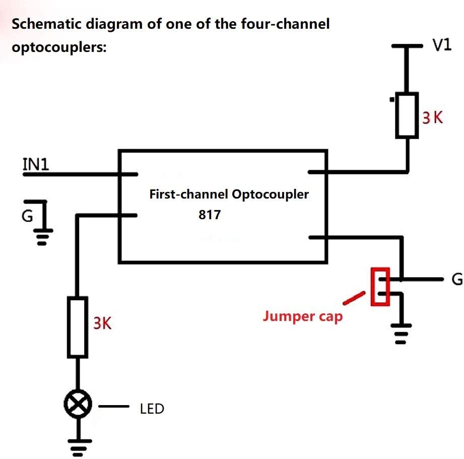
from this schematic,

on the input side i have ground going to tx of arduino nano pin. i have in1 connected to 5v. if i connect v1 to rx on the other arduino and gnd to gnd then nothing is working. if i install the jumper cap then i start getting messages on rx arduino but it deletes the isolation possibility.
I'm trying to research on this but im not having any good luck so far. can someone help me out here pleasee
for whatever reason i cannot understand what im doing wrong. after all there is only very few components here. When tx send a message the pc817 led illuminates. but without connecting the ground from both boards together i cannot get the message from sending side of the optocoupler board.
To get opto isolation, each Nano needs its own independent DC supply. I would reduce the value of the IRLED resistor to get more current transferred and higher speed.
Example:
Okay now i have a lot of questions. what is with -1.2 is this the voltage drop from the irled? is that -1.2 + -1.8 + -2 = 0v? is G1 there for a reason?