Hello everybody, ![]()
I am building a Useless Box using an Arduino Nano (for those who don't know what a useless box is, here is an example: Useless Box with Surprises - YouTube).
It is powered by 4x 1.2V AA batteries (4.8V).
My first setup used 2 switches: One "Top switch" controlled by the user & the servomotor arm.
One hidden "Power switch" to power the Arduino board, & the servos, in order to remove power when not being used (to save power).
The issue with this two switch configuration is that although it works well, it is not what I would call the "spirit" of a useless box: if you first have to power it up, that's not very fun !
Here is the above-described setup:

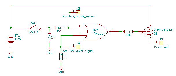
My idea is to modify this setup to only have one switch, on the top of the useless box. The user would close it, and it would distribute power to the setup. When it is opened (by the servomotor), the power should not be interrupted, so that the Arduino board can continue controlling the servomotors, keep its variables in memory, etc..
To do so, I use two new components:
- 1x OR gate
- 1x transistor
The switch, closed by the user, now sends a 1 signal to one of the inputs of the OR gate. As a result, its output goes to 1. This output is connected to the grid of the transistor, which controls the power distribution to the Arduino & to the servomotors.
As the switch will be opened by the servomotor, another way of controlling the power is needed, otherwise it would be interrupted: As soon as the Arduino is powered, it will apply a voltage to the other OR gate input, so that if the switch is opened by the servomotor, the state of the transistor remains unchanged:
The setup can now be turned on by the user "mechanically" and turned of by the Arduino "programmatically".
Hereafter is a representation of this improved setup:
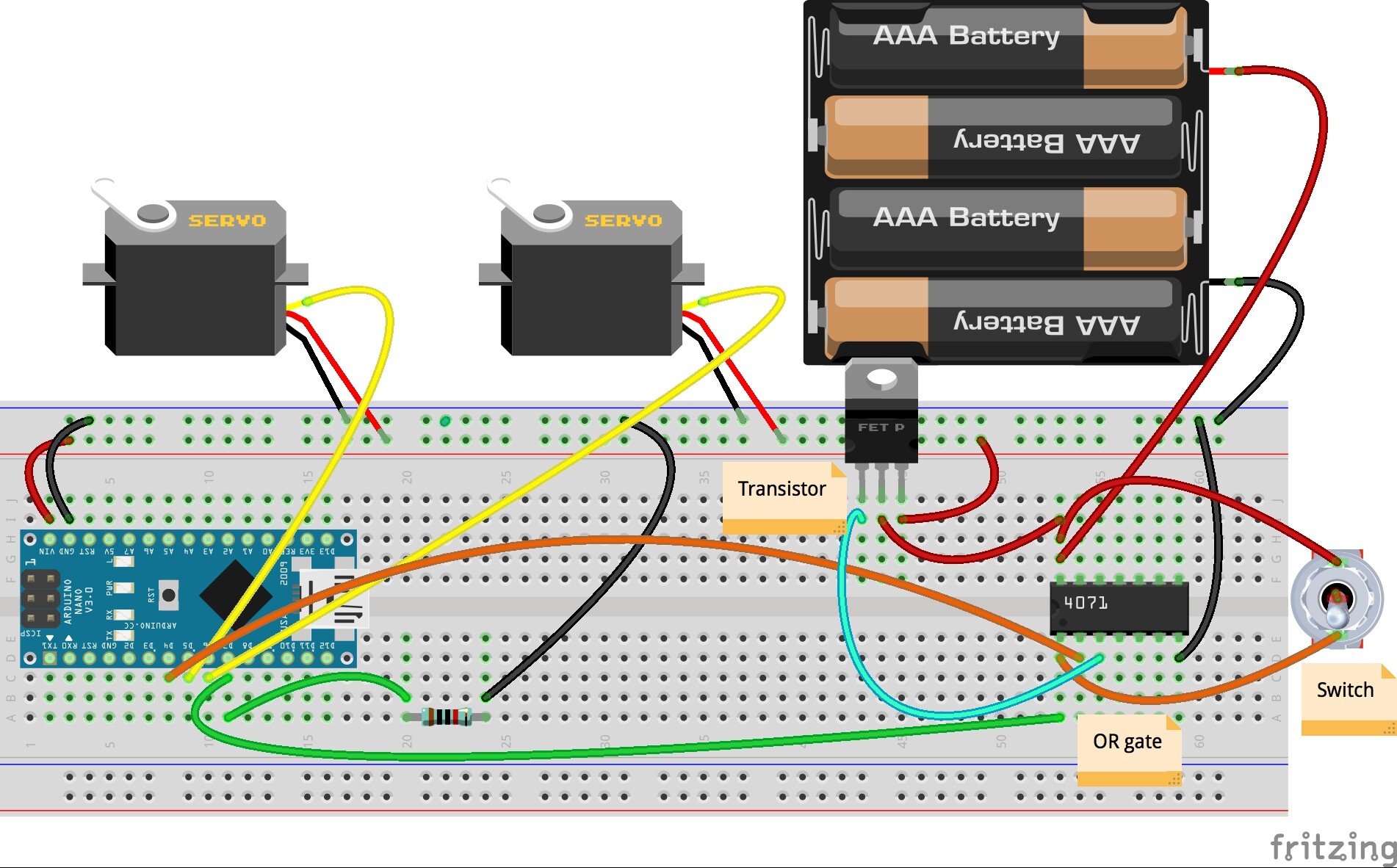
The components I used are the following:
OR gate: SN74HCT32
Transistor: IRFB4321PbF
Links to their data sheets:
OR Gate
MOSFET transistor
Now, here is my issue:
I don't get sufficient voltage from the transistor output.
Using a multimeter:
The OR gate outputs 5.11V when it is in its high state (0V when low), the output is connected to the grid of the transistor (this seems fair to me).
I have 3.95 V between the drain and the source. (This seems pretty high to me, as the grid is at 5.11 V).
Drain voltage is 5.11 V.
I only have 1.11 V of power available after the MOSFET (to run the Arduino & the Servos) => It won't work !
Now, I have never been an electronics specialist, and I might have poorly chosen my transistor.
Is it an issue with my setup or is it a transistor issue ? Which one should I use ? Are there alternative setups I could use ?
Your help would be highly appreciated ! Thank you very much !
Greg.