Odd question here - I'm using a bidirectional level shifter to have an Arduino running at 5V send serial data to an Arduino derivative (panStamp) running at 3.3V.
Ordinarily the level shifter is connected to both a 5V and 3.3V supply. If I am only sending data from a 5V TX to a 3.3V RX, do I need to connect the 5V supply? It seems like the 5V TX will hold the line high when idle.
I ask because I'm inserting this into an existing installation that has the 3.3V supply, 5V TX, and ground wired, but not the 5V supply. I could run another line but it would be easier if I didn't have to.
(And yes, I tried using a voltage divider to step the 5V TX down. I could never get it to work on the panStamp's hardware serial RX, though it would work on another pin with SoftwareSerial. Maybe something to do with the hardware serial pins also being connected to the USB-TTL chip on the panStamp carrier board.)
If I am only sending data from a 5V TX to a 3.3V RX, do I need to connect the 5V supply? It seems like the 5V TX will hold the line high when idle.
Yes, you must connect the 5V supply. (Try it without!). Otherwise, the 5V TX will not pass through the MOSFET when low.
A voltage divider should have worked. Perhaps you had the resistor ratios correct but the values were too high. No information was provided so I cannot help here.
Here are a couple of other ways to accomplish the conversion:
(1) Use three silicon diodes in series. 1N4001 diodes are cheap, and no power supply is needed.
(2) If the pin is to be low, digitalWrite(...) it LOW and set the mode to an OUTPUT.
If the pin is to be high, set its mode to an INPUT.
This assumes that there is a pullup to 3.3 volts at the other end. It also assumes that you have complete software control over the pin. If the pin is from hardware serial, this will not work. If the pin is from software serial, the library will have to be modified.
Yes, you must connect the 5V supply. (Try it without!). Otherwise, the 5V TX will not pass through the MOSFET when low.
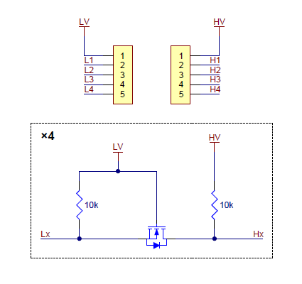
I'll try the experiment - but am still confused on why the high voltage connection is necessary. Here's the circuit:
Hx is driven either high or low by the 5V TX, right? So why would HV need to be connected?
A voltage divider should have worked. Perhaps you had the resistor ratios correct but the values were too high. No information was provided so I cannot help here.
I used 1K8 in the top and 3K3 in the bottom, values drawn from a post by Grumpy_Mike. This worked for a software serial RX, but not the hardware serial RX. The carrier board connects the hardware serial RX to a FT231XS USB-TTL chip.
You are correct (with the exception noted below). I had the HV and the LV swapped in my mind. I am sorry.
Professor Chaos wrote (in part):
Hx is driven either high or low by the 5V TX, right?
Exception: Prior to the pinMode() function being run for this pin, the pin connected to Hx will default to the INPUT state on some (all?) Arduinos. It could float to any voltage from 0 to 5 volts. Connecting 5 volts to HV will prevent this issue. If you can ignore the result (which could be some transitions from high to low and back) on the Lx side during this time, all is well. Note that you could do the equivalent at the Arduino if you have a roughly 10K resistor available.
Recovery time is unlikely to be an issue at 9600 bps or even 115200 bps.
When Hx is low, Lx is driven low through the FET. A pulldown resistor is unnecessary and will form a voltage divider with the pullup resistor that is connected to 3.3 volts.