Earlier I asked for help with my project and a lot of you chimed in. I now know a lot more about what you need to help and I am starting a new post. THANK YOU you help has pushed me much closer to my goal.
I have now set up an arduino with both a clock chip and a motor driver.
The stepper is a 200 step per revolution unit.
The clock chip has the ability to put out a 1 HZ signal on an as yet unused pin
Here is a video of the setup. Arduino Clock Motor - YouTube
Here is the sketch
//sketch to control a stepper motor with DRV8825 driver on breakuut boars
//Include the accel stepper library:
#include <AccelStepper.h>
// Define stepper connections and interface type. Motor interface type must be set to one when using a driver:
#define dirPin 5
#define stepPin 2
#define motorInterfaceType 1

// Create a new instance of the AccelStepper class:
AccelStepper stepper  =
AccelStepper(motorInterfaceType, stepPin,dirPin);

void setup () {
  // Set the maximum speed on steps per second:
  stepper.setMaxSpeed (1000);

}
void loop (){
  // Set the speed in steps per second:
  stepper.setSpeed(643);
  // Step the motor with a constant speed as set by ssetSpeed():
  stepper.runSpeed();

}
One of the suggestions I had was to have the arduino put out ten steps per second (the motor needs to turn at 3 rpm to drive the clock. 3*200divided by 60 = 10)
If the leading edge of the pulse made it put out ten pulses in just less than a second this should work great.
At this point I don't have the pulse out put connected to the Arduino and I am not sure how to go about it.
Help Please
So, to be clear, when you get an edge (+ve or -ve but not both) from the RTC, once every second, you want to output 10 pulses to the stepper driver in slightly less than 1 second?
Suppose the out pulses took 900 ms, then each one would need to take 90ms
So a simple way to do this is
continuously scan the pulse input comparing the new state with the previous
if a change is detected AND the change is from low to high then:
start a counter that runs for 10 cycles
for each cycle write a HIGH to the output pin for 45ms and a LOW for 45ms
go back to monitoring the input pin.
Code practically writes itself. I've used something rather like this for a very similar application.
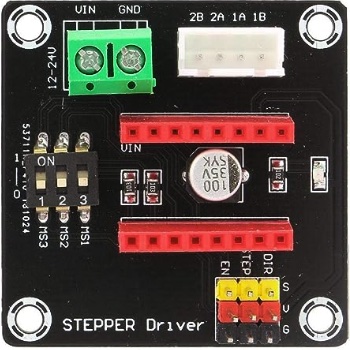
Ran into a snag last night. In order to make the clock quiet enough I am using a TMC2209 clock driver chip. It is mounted on a breakout board that looks like this
Notice that the micro stepping is controlled by three small slide switches. In my past experience when all switches are off the chip send pulses to the motor on a 1:1 basis. So I set it up to do 10 pulses per second which should translate to 3 RPM. To make a long story short I have to send approx. 80 PPS to get 3 RPM.
I have downloaded the spec sheet for the TMC 2209 which is 40 some pages long. Here it is along with the PDF of the TMC2209
The TMC2209 has only 2 pins to control the microstepping. Microsteps can be x8, x16, x32 or x64 (see here, Fig. 6) with the 2 MSx pins. Or you can set the microstepping through the UART.
Yes. I was able to get the motor to go at 3 RPM by setting the output to 80 steps per second.
How do I get the output of the clock chip in to the arduino and then get it to trigger the output.
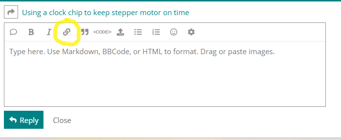
Another question. I uploaded the data sheet for the TMC2209 but it is not clickable. What am I doing wrong? I used the upload feature.
I think the Discourse software didn't add the datasheet using your method as it would have to print an 83 page datasheet in the post. (It does say that it is 1.8MB - my image was only 22kB.)
You can connect the Squarewave pin to an Arduino digital input. It is an open drain output, so you should use pinMode(xxx, INPUT_PULLUP); to use the Arduino's internal pullup resistor.
Using the techniques suggested by jhaine in post #6 (but modified for 80 pulses per second instead of 10), combined with the techniques in the StateChangeDetection example in the IDE it is possible to generate 80 pulses per second.
int outputPin = 12;            // Pulse output to stepperdriver
int oneHertzPin = 8;           // RTC one Hertz output connected here
int oneHertzState = 0;         // current state of the RTC output
int lastOneHertzState = 0;     // previous state of the RTC output

const long interval = 6;       // half the pulse period, 80 pulses = 960ms

void setup() {
  pinMode(outputPin, OUTPUT);
  pinMode(oneHertzPin, INPUT_PULLUP);
}

void loop() {
  oneHertzState = digitalRead(oneHertzPin);
  if (oneHertzState  != lastOneHertzState) {
    if (oneHertzState == HIGH) {
      for (int i = 0; i < 80; i++) {
        digitalWrite(outputPin, HIGH);
        delay(interval);
        digitalWrite(outputPin, LOW);
        delay(interval);
      }
    }
    lastOneHertzState = oneHertzState;
  }
}
This looks great. I combined it with the stepper program. My plan is to simply switch the connection from pin 2 which is the step output to pin 12. I don't know what the direction signal looks like but if it is a constant (since the motor only runs in one direction) it should trigger the motor driver. When I tried to send it to the Arduino it said oneHertzState was not declared. How should that be done? Do I not need any additional library for this to work?
Here is the sketch
//Include the accel stepper library:
#include <AccelStepper.h>
// Define stepper connections and interface type. Motor interface type must be set to one when using a driver:
#define dirPin 5
#define stepPin 2
#define motorInterfaceType 1
int outputPin = 12;
int oneHertzPin = 8;
int oneHertzStat = 0;
int lastOneHertzState = 0;
const long interval = 6;

// Create a new instance of the AccelStepper class:
AccelStepper stepper  =
AccelStepper(motorInterfaceType, stepPin,dirPin);

void setup () {
  // Set the maximum speed on steps per second:
  stepper.setMaxSpeed (1000);
pinMode(outputPin, OUTPUT);
pinMode(oneHertzPin, INPUT_PULLUP);
}
void loop (){
  // Set the speed in steps per second:
  stepper.setSpeed(80);
  // Step the motor with a constant speed as set by ssetSpeed():
  stepper.runSpeed();
  oneHertzState = digitalRead(oneHertzPin);
  if (oneHertzState !=lastOneHertzState)
  {
    if (oneHertzState == HIGH) {
      for (int i = 0; i < 80; i++) {
        digitalWrite (outputPin, HIGH);
        delay (interval);
        digitalWrite  (outputPin, LOW);
        delay(interval);
      }
    }
    lastOneHertzState = oneHertzState;

      }
    }
  }

}


type or paste code here
Bit late to the party.
I see you step faster, and then wait for the RTC pulse to arrive.
I porbably would have done it differently.
let the RTC advance a counter.
let step pulse (divided by microstepping) advance a second counter.
compare the two counter values, and let the result correct the setSpeed value.
That way motor speed is always constant.
I assume the clock is indoors, with WiFi available.
An ESP8266 board could have provided those clock pulses more accurately, and no RTC or extra hardware would have been needed.
Leo..