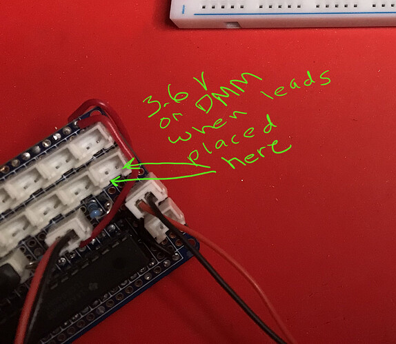
I have a small chunk of an 12V LED strip that I'm wanting to control from small voltage emitted out of one of the output pins from a TLC5940. I'm using a 2N2222 transistor to switch the 12V led on and off. The circuit is "working" but the LED is not getting the full 12 volts, instead it seems to be getting about 8.9V. I think this is due to me only supplying a smaller voltage from the 5940 outputs, specifically about 3.6V. These output are all driving other individual SMD LEDs so I can't really change the 3.6V at this point. Is there a better transistor or MOSFET to use so that I can get the full 12V? I came across mentions of using something like an IRL520 or IRL540?
I've attached a circuit diagram, hopefully I've notated it correctly.
Thanks for the schematic. All that and no value for R1, probably the most pertinent to your question? I also see no common ground between the transistor emitter and the 12V battery. Schematic oversight or real?
Why did you feel compelled to criss cross the lines around the battery?
Why? BJT's are current driven not voltage driven devices.
Probably because its the first circuit I've done and the first time I've ever used Eagle and still getting used to it. I'll fix it. Yes R1 was an oversight, sorry.
The emitter ground ties back into the 5940 and I wasn't sure how to notate that?
I tried a couple of different values for R1, 100 O, 4.7K O, none of them made much of any difference, and I'm pretty sure I don't completely understand this.
Then please either use pen and paper to make a more accurate diagram, or post images of the actual hardware. Or both.
Eagle? First circuit? You should be making a prototype first. Even professionals would usually do that. But, if you did design and order a PCB we need to see it.
Updated the diagram
No PCB, I made a breadboard prototype. I'll take a pic in just a bit
TLC5940 has LOW true (sinking) outputs, won't work with NPN.
Datasheet page 11, figure 9:
https://www.ti.com/lit/ds/symlink/tlc5940.pdf
Just FYI, that is a forum no-no. It makes nonsense of the replies. Post in a new message next time.
OK, but it does work. Does that mean there's something else wrong? Or perhaps I've wired things backwards?
5V into the barrel jack is not okay.
I just looked around and I guess I can just feed this to the 5V pin. Didn't realize I could do that.
Yes you should do that.
A very small voltage indeed! The TLC5940 is not supposed to generate any output voltage at all, so I cannot imagine from where you get that 3.6V! ![]()
Now an Arduino Nano as implied on your diagram has 30 pins, not 32 and pins 1 and 30 are definitely not Vcc and ground, so that diagram is definitely not a description of a real project!
OK, it's a UNO.
Clearly the TLC5940 cannot drive LEDs connected to ground as implied, so this is all rubbish so far! ![]()
I think I will leave this thread alone for the present. ![]()
The conventional notation for that would be "100R"
Ω
Alt-code '234'
Then could you please explain why it's lighting up the LED Strip? Can you please explain why when I plug in the other SMD leds, that they all light up? How is this rubbish? I'm trying to provide as much info as I can and the best you can do is be insulting? WTF?
Data sheets don't lie (usually!). What does it say? ![]()


