I´m new here and have started my self-learning project building up a solar tracker robot. I was going well until I wanted to add the HMC5883L Module to get the heading of my robot.
Since all my analog pins of my Uno are used (2 for joystick and 4 for photo resistors) I thought I can use the SCL/SDA pins at the opposed side to connect the HMC5883L.
But then I get strange readings or malfunctions when all the pins are connected.
E.g. if I unplug the analog pins, the sensor readings come in perfectly. When I connect the analog pins, the serial monitor stalls. But just now it was working great even with the analog pins were plugged in. Then I left for a coffee, and now the values are frozen but get refreshed when I turn the sensor around (but always the same value)....I really do not get behind this problem and would highly appreciate some help
With the Sensor I have two more issues.
When I use the example "magsensor.ino" code for the Sensor I get this message when converting it...but the code works anyways.
In the code above these two expressions are used with the "void" inside the () as well...
void setup(void)
void loop(void)
When I include this content to my main code with standard "void setup()" and "void loop ()" it does not work without the "(void)". I do not understand what’s behind the (void) and would also need some help to get this fixed as well.
You cannot use the pins simultaneously for analogRead() and as I2C SCL/SDA (digital).
These are complete different kinds of signals (and probably input output conflicts)
You might try to put an I2C multiplexer in between e.g.
I moved your topic to an appropriate forum category @ben7982.
In the future, please take some time to pick the forum category that best suits the subject of your topic. There is an "About the _____ category" topic at the top of each category that explains its purpose.
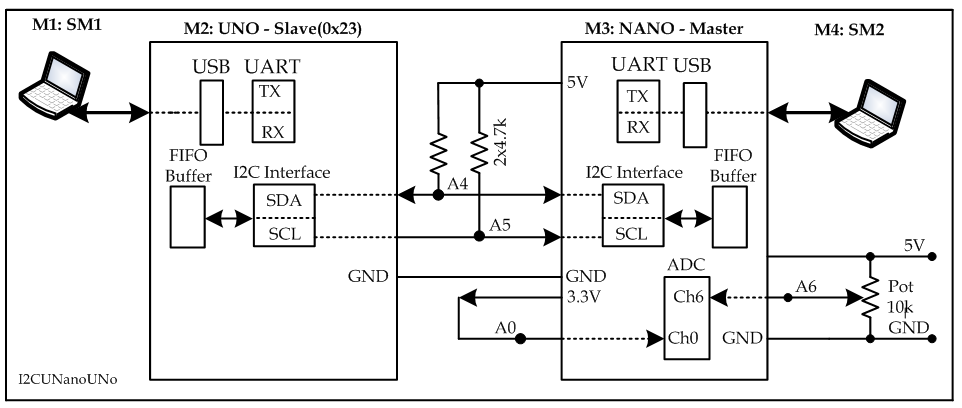
You can use an Arduino NANO (Fig-1) which has 8 analog channels; you use A0 - A3, A6-A7 for your analog sensors and use A4 (SDA)/A5 (SCL) lines as I2C Bus for HMC5883L sensor. Arduino NANO is the same as Arduino UNO but of smaller form factor and extra two ADC channels. This is an idea which I never tried, but I am testing now and it works.
Figure-1:
Test Sketch: (tested using NANO-I2C Master and UNO-I2C Slave)
In this sketch, NANO (I2C Master) is acquiring 1-byte data from I2C-Slave(0x23), ADC-Ch0, and ADc-Ch6 at 1-sec interval. Note that analogRead() function does not support ADC-Ch6 and ADC-Ch7.
Oh WOW, thanks so much for your quick replay and very helpful advice!
Especially to Golam Mostafa for your time and effort to code and test an alternative solution!
And sorry for messing up the category.
So there is no way to tell A4/A5 to listen only to analog readings while using the designated SCL/SDA at the other side…that’s a pity.
I also have a ESP8266 Mega-Board laying around but it keeps telling me an upload error “avrdude: stk500v2_ReceiveMessage(): timeout”
The seller told me to get the jumper/switch-settings right, but out of my view they are good and as shown in the instruction under this link he sent me.
(Switch 1,2,3,4,8 off and 5,6,7 on, since there is no aditional jumper supplied, I guess that’s it).
In my opinion the Mega would be the easiest way to solve my pin-issue.
What about the other two issues I have mentioned [“(void)” and “uint8_t”]?
Hopefully, the following diagram (Fig-1) will establish that it is the feature (NOT limitation) of the ATmega328P MCU of the UNO board for not emitting/handling I2C signals over the SDA/SCL pins of the edge conncetor while A4/A5 lines are expected to handle ADC-Ch4 and ADc-Ch5 signals.
The designated SDA/SCL lines maintain parallel connections with A4/A5 lines; hence, in I2C Bus mode operation, the A4/A5 lines are essentially I2C Bus lines being connected with I2C Module of the MCU.
The diagram also demonstrates that the physical pins (27/28) of the MCU can be routed to one of the four internal modules; hence, it is not possible for these pins to handle the operations of ADC/I2C Modules at the same time.
Thanks to the MCU Designers fo accomodating so many alternate functions over two physical pins of the MCU!
I understand the wiring now but I cannot see any benefit of the two designated SDA/SCL pins, then...maybe this makes sense for some advanced coding but as a beginner I do not understand the additional pins when I cannot use the A4/A5 as analog pins in parallel.
Thanks to your post and mentioning the ATmega328P I suddenly understood the uploading problem with my Mega-Board as well. I needed to set the switches like this to upload via USB to the Chip (ATmega2560) [1,2,5,6,7,8 off and 3,4 on]. Now the upload works great and I´m happy having 15 analog pins now .
Now I need to get the issues solved with the coding [“(void)” and “uint8_t”]. Should I open another thread in the designated category or why is nobody picking up on these ones?
The additional SDA/SCL designations are provided for the benefit of new Arduino Programmers for quick connection of the I2C devices. Later on as experiences grow, they understand that SDA/SCL = A4/A5 (for ATmega328P based UNO Board) and that these lines provide either I2C services or ADC services and NOT both at the same time. Edit
When the IDE 1.18.19 comes on, the following blank sketch apperas with two empty functions:
void setup() {
  // put your setup code here, to run once:

}

void loop() {
  // put your main code here, to run repeatedly:

}
I don't see anything like void setup(void) and void loop(void).
If you have studied a course on C Programming Language, you have certainly come across the following concepts to understand the reasons of associating void (nothing/none) associated with the above setup() and loop() functions:
Value passed by the Calling Program to the Called Program.
Value retured by the Called Program to the Calling Program.
uint8_t
It is a "data type" which is equivalent to "byte". It is used to state the variable being qualified by this keyword can hold hold only positive (unsigned) value of the range: 00 - 255 (0x00 - 0xFF).
Then why uint8_t instead of byte?
Let us try to get the answer using uint16_t type.
In Arduino Platform, the unsigned int type is always a 16-bit space for ATmega328P MCU of the Arduino UNO Board.
In Arduino Platform, the unsigned int type is always a 32-bit space for SAM3X8E MCU of the Arduino DUE Board.
So, while working with 16-bit data in DUE board, we use uint16_t type to indicate that the operand being processed is truly a 16-bit item.
Additionally, not all Arduino boards use A4/A5 for SDA/SCL, depending on the processor used on the board. The dedicated SDA/SCL pins then allow a common connection point regardless of which pins are actually used.
Thanks a lot for explaining the SDA/SLC fully. Now I got it!
I know what “void setup()” and “void loop()” does, but my c++ class at university is too long ago and was not very memorable either. So it’s more like starting from zero…
I just never came across “void setup(void)” or an “void loop(void)” before I opened the example code “Adafruit HMC5883 Unified à magsensor” to test the HMC5883L
I do not understand the “void” in brackets…
And I do not understand the error this code is giving me when compiling, but runs anyways.
In the meantime I managed to integrate parts of the example code into my main code of the robot.
I created a own “void compass(void)” and call it up when I need it… but I still don´t get what the “(void)” is for, but if I put only “void compass()” it´s not working…
I´m off for some freshly baked cinnamon rolls and testing the robot in the barn
The "(void)" part isn't required. void loop();void loop () will do.
The variables of a function's returned values, when they are used, are placed inside the parentheses.
We use a lot of C++ forms, but there are a lot of Arduino functions that make things easy -- digitalWrite(), analogRead(), and so on, that aren't part of a C college course.
I did not came up with the (void), it is included in this official example I mentioned. Please open it up at your side and check it out. When you compile it, it will bring a lot of the “uint8_t” errors….that´s my problem.
Besides I´m totally with you that void loop(){} //will do and that’s what I´d expect from official side.
But in this case it does not work and I have no clue what’s behind that…