The module is a 20x4 LCD and has 7 key switch attached to the module.
Using an Arduino I2C scanner, I found that the board is using these I2C address. I unplugged the module, the scanner respond with no I2C address found.
0x20
0x21
0x22
0x2C
I did copy and installed library and code, and run it on the Arduino. Nothing is displayed.
Looking for help me to progress in the installation of the display and get access to the key switch.
This is my first attempt with Arduino. I did played 15 years ago with processor of the Intel family 8259 and I2C. I'm a bit rusty, but do understand.
I'm green Let be honest... I know very little about:
Arduino
Library
This particular LCD
Bough the LCD 12 years ago but never used it.
I installed an I2C LCD library from the Arduino link and modified the I2c address to 0X20.
First taught that all LCD where similar / plug&play.. wrong.
I realised now that I will probably need to find or create a specific library for this model. Or buy a more recent I2C LCD module.
What I observed:
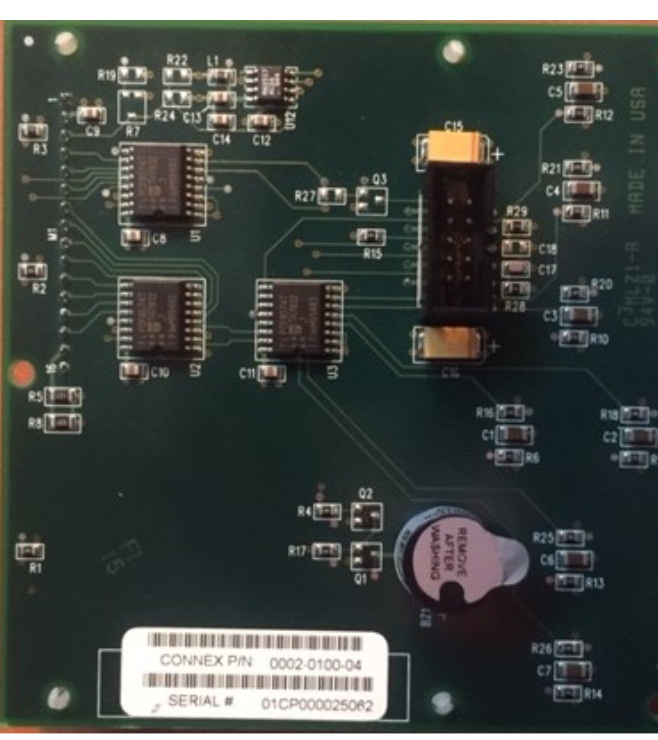
There is three I2C address found with a scanner
The contrast is driven from a MAX517 DAC on the module
There is 3 PCF8574T IC that are driving
OK, if it is using PCF8574s, then the HD44780 library stands a fair chance of operating it, or Bill may even choose to add support.
And it has a piezo sounder!
Bit of an odd design though - of the three PCF8574s, one drives the LCD control pins and I presume the DAC, one gives 8-bit data to the LCD and the third reads the buttons and controls the sounder. Rather gross over-design (especially using a DAC)!
No, the MAX517 is itself I2C, so must own the fourth address, 0x2C. Ridiculous!
Hmm, I wonder if it has continuously variable illumination using the second DAC output?
U1 controls RS, WR, EN, possibly backlight, unmounted Q3
U2 controls 8-bit data bus i.e. DB0-DB7
U3 probably reads 7 user buttons and possibly buzzer via Q1, Q2
I have no idea what U12 does.
One thing is certain. I2C code will not work like a regular PC8574 backpack.
The board appears to come from the USA. Perhaps the designer was on heavy medication.
The idea seems quite interesting. But a lot easier to have a single intelligent MCU e.g. like UART/SPI/I2C backpacks.
That device is not going to work with any Arduino LCD library that I know of.
I am a bit confused though. Where did the photo of the working LCD in first post come from?
What s/w and h/w is driving the LCD module?
If you want to get it working with Arduino, IMO, the easiest thing to do would be modify the board to make it look like an I2C backpack, then use the hd44780 library.
It would involve cutting 4 traces on u2, 3 traces on u1, and adding 3 wires (I'm assuming that backlight control doesn't exist) from U2 to the LCD for the LCD control lines, (RS, /RW, E).
Not too difficult if you have a find tip soldering iron, and decent soldering skills.
If you don't want to modify the h/w, you could also write a new hd44780 i/o class for it.
bperrybap:
That device is not going to work with any Arduino LCD library that I know of.
I am a bit confused though. Where did the photo of the working LCD in first post come from?
What s/w and h/w is driving the LCD module?
If you want to get it working with Arduino, IMO, the easiest thing to do would be modify the board to make it look like an I2C backpack, then use the hd44780 library.
It would involve cutting 4 traces on u2, 3 traces on u1, and adding 3 wires (I'm assuming that backlight control doesn't exist) from U2 to the LCD for the LCD control lines, (RS, /RW, E).
Not too difficult if you have a find tip soldering iron, and decent soldering skills.
If you don't want to modify the h/w, you could also write a new hd44780 i/o class for it.
--- bill
Resolved;
beperrybap,
I did the proposed modifications and yep it work. Cut the wires for the 4 upper data pin and the 3 lcd control. Soldered wires from to the U2 pin 4,5,6 to the LCD control pin. I did not installed the contrast pot