I am trying to control an linear actuar with a dc motor including limit switches. To switch direction I use a relay board to create a H bridge. Like in the drawing below. When I switch direction to fast(every half second or so) my relay board will trip. I read somewhere that those 8 relay boards have a maximum switching frequency from 30 times a minute. When you go faster than that electrical feedback can cause problems. Is it about the maximum switching frequency of my relays or about the deceleration of my motor? In all applications that I found online everyone is using a 2 second delay before switching direction. Does it mean I can't go faster than that?
Hope someone can explain me a little bit more why I can't switch direction faster or how I can.
Tripping relay board is something new to me. How does that look like?
I would apply a PWM transistor, a logic level N channel MOSFET on the low side of the motor. Changing direction before the motor has stopped looks bad to me.
What do you mean with "my relay board will trip" ? Can you be more specific?
If you have a board with 8 relays, I know form experience that (for example) an Arduino Mega cannot provide enough power to power all relays. So it is very well possible that the power supply of your Arduino is on its knees and that this is the source of the problem. Have you measured the overall current consumption/voltage level of your setup?
Secondo: Can you provide an electrical drawing of your test setup so the forum members can look into it?
A relay is a mechanical device. You need to energize a coil to physically open or close a contact. This takes time and is orders of magnitude slower than how fast a microcontroller can send signals.
@blh64 Correct. Often the time to deenergize a relay coil is underestimated. Read the data sheet seriously.
Also, don't forget about giving motor kick back diodes time to do their job, or make the motor stop before changing direction.
Thanks for the replies already, I will try to post a schematic tomorrow. With trip I mean that the relays will not work until I power down and up again. I switch only 3 of the 8 relays and have te relay board separately connected to the supply. When I disconnect the linear actuator. Everything stays on. Only when I connect it back and change direction to fast it will stop working. I got the feeling that it happens because the motor is not in standstill and than I change direction.
Thanks again and I will come back to this tomorrow
Likely the motor has an inductive component in its characteristic. Such loads need a kick back diode to kill the energy generated by the spinning motor.
I recommend a kick back, fly wheel diode, between GND and +12, and that You don't change the relays before the motor has stopped. Else there will be sparks and they create Rf disturbance tilting all kind of digital logic.
How much quick you need to stop it, and how much big is the motor ? ... industrially, when a similar configuration was used (in old control boards, now almost anyone uses bridges), sometimes was added a third relay that briefly short the motor with a low value resistor for stop it more quickly (electromagnetic brake) ...
Your configuration do the same thing, but directly, ending with high current spikes that can easily glue or damage the relay contacts (all the energy is shorted from the relay contacts directly when turned off ... if is a very small motor that may not be a problem, but with bigger motors it is)
Anyway, the better way for increase speed remains using an H-bridge, preferably mosfet, with the correct timing in the activation sequence (for prevent the possibility that 2 mosfet of the same side turns on together shorting the power supply, and adding a braking system with external mosfets and resistor if quick stop is needed)
It's a small 30watt maximum, 12v motor. It doesn't need to stop super fast. I would like to switch direction in a second. It's used for steering a small boat. I included an image of the motor and my initial setup. I now use a esp32 with bluetooth to connect it with my app. To control the relay board I use a mcp23017.
Etemenanki:
How much quick you need to stop it, and how much big is the motor ? ... industrially, when a similar configuration was used (in old control boards, now almost anyone uses bridges), sometimes was added a third relay that briefly short the motor with a low value resistor for stop it more quickly (electromagnetic brake) ...
Your configuration do the same thing, but directly, ending with high current spikes that can easily glue or damage the relay contacts (all the energy is shorted from the relay contacts directly when turned off ... if is a very small motor that may not be a problem, but with bigger motors it is)
Anyway, the better way for increase speed remains using an H-bridge, preferably mosfet, with the correct timing in the activation sequence (for prevent the possibility that 2 mosfet of the same side turns on together shorting the power supply, and adding a braking system with external mosfets and resistor if quick stop is needed)
I saw the BTS7960B h bridge module. I'm gonna try this one out.
Are you referring to the complete board, not the single chip, i suppose ... then consider that the "43A" mentioned from all the seller is not realistic ... they just copied the maximum rate mentioned in the datasheet, without keep in consideration any other thing, especially thermal derate, power dissipations, and so on ... as their usual
considering the initial data of approximatively 20 milliohm that the chip can have (high + low side, around 30 degrees, but it increase when temperature rise), if i put 40A in that board, obtain to have 0.8V dropout and around 32W of thermal dissipation ... this will increase rapidly the temperature and start usual positive feedback (temp increase > RdsON increase > dropout increase > power dissipated as heat increase > temp increase ... and so on) ... without a forced cooling system, it may lead easily to pass 150C and trigger thermal protection shutdown ...
But for a 30W motor it may be enough with the standard heatsink gave with these boards, if air is free to circulate ... anyway, also if these chips already have internal deadtimes generators (for commutation safety), is better if you delay the inversion around half second ... say, turn off > wait 400 or 500 mS > turn on in the opposite direction ... the mechanical resistance of the gears inside must be enough for stop the motor completely (or almost completely) in this time ...
Etemenanki:
Are you referring to the complete board, not the single chip, i suppose ... then consider that the "43A" mentioned from all the seller is not realistic ... they just copied the maximum rate mentioned in the datasheet, without keep in consideration any other thing, especially thermal derate, power dissipations, and so on ... as their usual
considering the initial data of approximatively 20 milliohm that the chip can have (high + low side, around 30 degrees, but it increase when temperature rise), if i put 40A in that board, obtain to have 0.8V dropout and around 32W of thermal dissipation ... this will increase rapidly the temperature and start usual positive feedback (temp increase > RdsON increase > dropout increase > power dissipated as heat increase > temp increase ... and so on) ... without a forced cooling system, it may lead easily to pass 150C and trigger thermal protection shutdown ...
But for a 30W motor it may be enough with the standard heatsink gave with these boards, if air is free to circulate ... anyway, also if these chips already have internal deadtimes generators (for commutation safety), is better if you delay the inversion around half second ... say, turn off > wait 400 or 500 mS > turn on in the opposite direction ... the mechanical resistance of the gears inside must be enough for stop the motor completely (or almost completely) in this time ...
Thanks for the background info! I ordered a complete board indeed. Today I did some more tests. The strange thing is that I also have the behavior when only powering on in one direction. When I turn on the relais without the motor connected everything is fine. But even when I use the relais only for powering on the motor. It will sometimes deactivate my other relays or even activate them. Seems that there is some noise or something might affecting my mcp23017? I will upload a movie from the behavior tomorrow.
Due to the circuit You use, with relays, I think 4 diodes would be needed. Both motor terminals needs one diode connected from - up to the motor terminals and also diodes connected up to +12.
If You would use a H bridge this would be build in in the bridge.
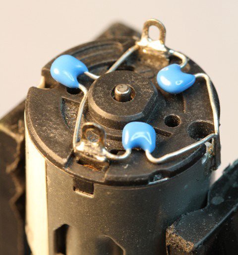
If you have access to the motor pins (where the wires are soldered), you can also add capacitors at it (as near as possible, normally are soldered directly on the motor) ... 3 capacitors soldered as in the pic usually take care of the sparks and EM noise generated from the brushes ... one is soldered between the 2 pins and the other 2 from each pin to the metal case ...
If metal case is not possible to be soldered, one capacitor between the pins and a pair of ferrite inductors from pins to wires also may help ... like these ones ...
For the bouncing contacts probably snubbers (RC in series, say, 100n with 47 ohm) on the contacts may help a bit, but need to be tested ... and a fast diode (schottky) can also be soldered directly on + and - inputs of the relais group (cathode at + ofcourse), but in that position i don't know how much they can help ...
As alternative you can replicate the protections used in H-bridges ... for each side of the motor, diode from pin to +V (catode at +V, anode at pin) and diode from pin to -V (anode at -V, cathode at pin) ...
That is a mechanical system, not a free-running motor, this means the motor become partially brake from the mechanic assembly ... once you grant at least half second of pause in the middle of an inversion of direction, it must be enough for stop the motor enough for prevent damages to the bridge ...
You can also use PWM with the H_bridge, so opposite that with the relay, you can also regulate the speed, and introduce some sort of PID control ... but this is software part ...
Etemenanki:
That is a mechanical system, not a free-running motor, this means the motor become partially brake from the mechanic assembly ... once you grant at least half second of pause in the middle of an inversion of direction, it must be enough for stop the motor enough for prevent damages to the bridge ...
You can also use PWM with the H_bridge, so opposite that with the relay, you can also regulate the speed, and introduce some sort of PID control ... but this is software part ...
The H bridge is doing its job! Working fine now. Thanks! To control the actuator I use a joystick with 4 micro switches. I use a pc817 optocoupler board to use it with 12v. But one of the microswitches is always on. I measured resistance and when it's open I still measure high resistance. I thought it would be a broken switch so I replaced it. Then resistance was infinity again. After a day of testing, today happened the same thing. I now measure resistance again when the switch is open. Any idea?