Hi guys!
This is my first post and in gonna be 100% honest here. I'm building a remotely controlled motorized clamshell dome for my telescope. It's been one insanely huge project so far. The done is done, all the mechanical engineering is done, the belt system thats driven by two DC motors is done. What's left is the in my opinion overly complex part of controlling the shells that glide over each other to fully open the dome and to close it.
I have purchased:
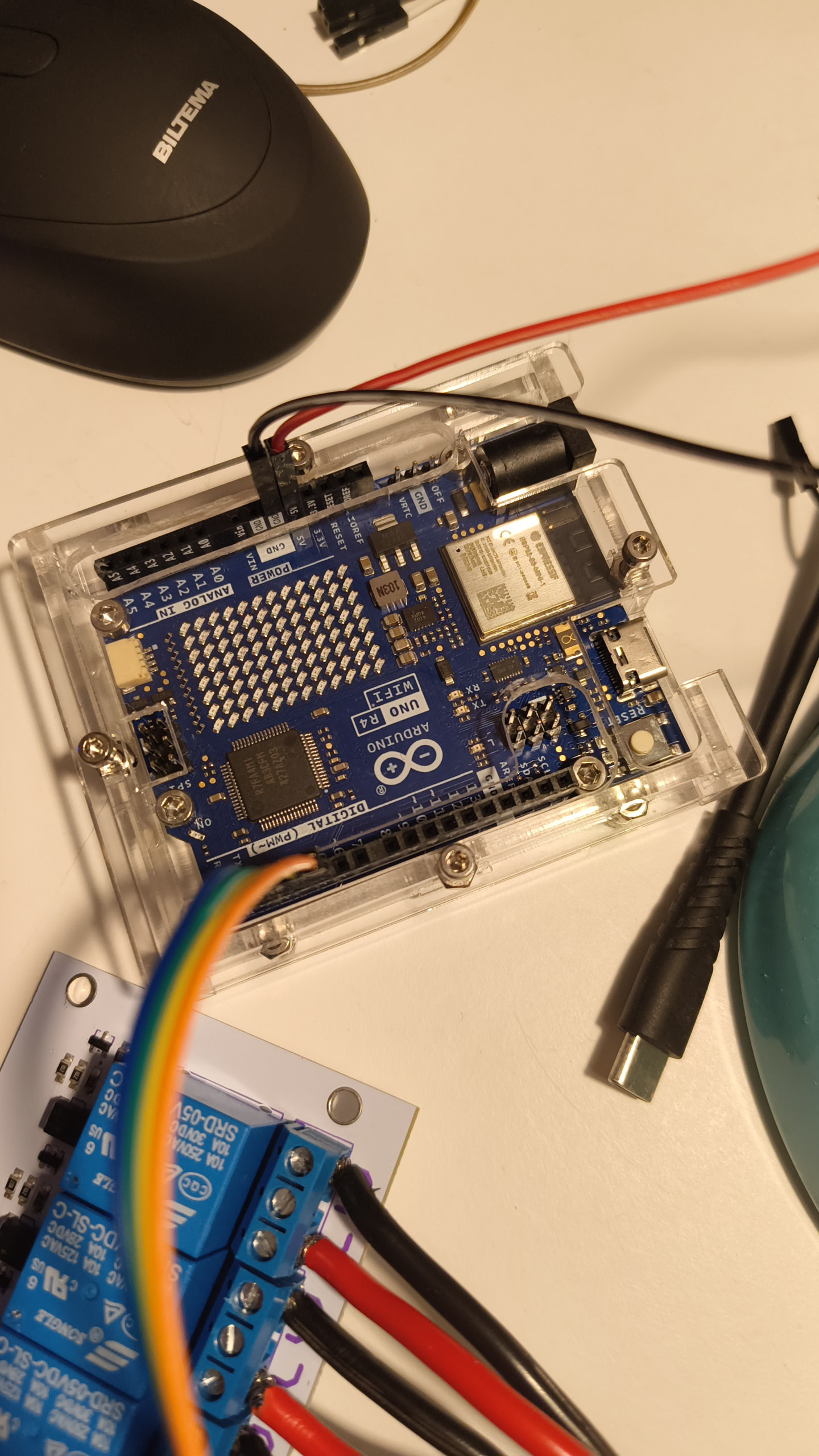
Arduino Uno R4 WiFI
Luxorparts 8ch relay
Mean well 12v 26.7a powersupply
And I have the two DC motors. They are actually 24v but I have tried a few times to get this working but I have messed up two times and long story short one 24vpowersupply and two relay boards are now in EL-heaven ![]()
![]()
I did the H-configuration wiring, compiled a code with help from AI and it worked. I could open and close the shells and I thought I was all good I could run the DC motors separately, forwards and backwards..
the next day I was gonna work out some konkurs on the mechanical side of the system and find out exactly how long my motors had to run to open and close perfectly, but after a few runs, one of the motors just continues to go with no response when trying to stop it.. after examining the relay board I found some bad thing.. long story short, I don't know what the hell I did wrong. I'm thinking maby, my 24v connections to the relay was a bit loose?
I have now purchased a new 8ch relay board, and I have went over the wiring, and made sure it's alle 100% but I get stuck at one point. My 8ch relay board don't have a JD/VCC pin. It have the VCC,GND,in1-8 AND GND/COM pins Wich have a jumper on them. Im guessing maby my mistake was to leave this on?
I hope someone can please help me out here because I'm really pressed for time her... I'll attach a bunch of pictures.
If something is unclear. What I'm wondering is Wich pins do I use FROM the Arduino Uno board, what do I do with the jumper, and how do securely and safely use my 12 powersupply for this project? ![]()
![]()