Hi there. I have bought some EEPROM and am confused by how to address it since there are no address pins. I have consulted the datasheet but its beyond my ability to comprehend unfortunately.
I tried using the 'sparkfun external eeprom arduino library' regardless and after running the basic Read/ Write example it seems that the software was able to detect the IC because i got:
Qwiic EEPROM example
Memory detected!
Mem size in bytes: 64000
I read: 255
the problem is that whatever number i try to write, the result is always the same (255)
here is the arduino code:
#include <Wire.h>

#include "SparkFun_External_EEPROM.h" // Click here to get the library: http://librarymanager/All#SparkFun_External_EEPROM
ExternalEEPROM myMem;

void setup()
{
  Serial.begin(115200);
  Serial.println("Qwiic EEPROM example");

  Wire.begin();

  if (myMem.begin() == false)
  {
    Serial.println("No memory detected. Freezing.");
    while (1)
      ;
  }
  Serial.println("Memory detected!");

  Serial.print("Mem size in bytes: ");
  Serial.println(myMem.length());

  //Yes you can read and write bytes, but you shouldn't!
  byte myValue1 = 42;
  myMem.write(1, myValue1); //(location, data)

  byte myRead1 = myMem.read(1);
  Serial.print("I read: ");
  Serial.println(myRead1);


void loop()
{
}
so im not quite sure where to go from here. I've included the circuit for reference. Many thanks.
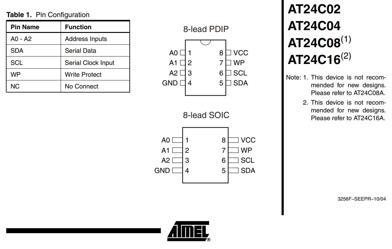
Without telling us the part number, the best we can offer is that you look for a section like this in the datasheet for your part.
I would connect the NC pins to a Low Level (such as 10K resistor to Gnd). 1,2,3 are the address select lines, 7 is Write Protect. It needs to be Low to allow data writing.
There will be a fixed part of the address 0, in this case the upper 4 bits are 1010
Then 3 bits to select 1 of 8 pages of memory in the chip, start at 0 there
Then the R/W bit, high for read, low for a write.
So your I2C address to write to page 0 of the chip would be 0b10100000
and for a read 0b10100001.
Then the I2C message would include the actual address within the page.
The photo shows what looks like the SOIC package version which isn't very beginner friendly from the point of view of wiring it up. Unless of course you've got a steady hand and reasonable soldering skills.
Once you have the chip connected, I would suggest that your first step is to run an I2C scanner sketch on your Arduino and see what address the EEPROM is using.
The example code you have found doesn't look like it is working quite right as it is reporting that there are 64000 bytes, which is a strange number. For your chip I would have expected it to say 2048 bytes.
ok ive now updated the circuit so that pin 7 (WP) is connected to GND which should disable write protection. I have also connected pins 1,2 and 3 to GND which as I have should set the device address to '0x50'.
I have used the following code which came from this tutorial:
If your read the data sheet carefully, it appears that there are two different versions of that eeprom -- one with Vcc 4.5-5.5v and the other with 2.7-5/5v.
Your diagram indicates that you are working at 3.3v. Are you certain that you have the low voltage version of that eeprom?
disk1 is only a byte, the function treats it as an int, maybe something odd is happening there.
I tried changing the device address argument to byte and still the same deal unfortunately. I'm still a bit confused about the which version of the IC i actually have(Yes i know this is the problem from buying from chinese markets). The markings say 24C16N. the first datasheet which i get when i search for AT24C16 is this one which suggests that the IC cant run at higher than 3.6V and makes no reference to the address pins. then there is this one which looks more familiar and allows 5v power. However i have tried hooking up the IC to 5v and im still just getting the same scenario, write function not having an effect(only ever reading 255)
I've just connected up an Arduino UNO clone and a ZS-042 RTC & EEPROM board. The EEPROM is allegedly an Atmel 24C32N, but who really knows as my ZS-042 board is quite likely to have come out of China as I bought it on ebay ages go. The ZS-042 module is powered from the UNO +5V supply.
The EEPROM device on the ZS-042 board has the following markings on the top of the chip:
ATMEL332
24C32N
SU27 D
I downloaded the Sparkfun library that you are using. I had to make 1 change to the Sparkfun Basic Read Write example in order to get it to work with my particular setup. The Sparkfun example assumes that the A0, A1 & A2 pins are grounded, giving an I2C address of 0x50 for the EEPROM. My board has A0, A1 & A2 pulled high via a resistor pack so I just changed the default address to 0x57.
I ran the example code with the above mentioned modification and the serial output was:
Qwiic EEPROM example
Memory detected!
Mem size in bytes: 64000
I read: 200
I read: -366
I read: -7.35
Ignore the memory size as that's a default value in the library. The 3 values are correctly written and read out of the EEPROM.
EDIT: I've looked through quite a few Atmel (not Microchip) datasheets for their EEPROMs and the datasheets that gave part markings did not have any that matched the format of the markings on either your chip or mine! I guess we've both got clone devices.....
Just in case you think it might be a problem with the Sparkfun library, here's a bit of code I threw together that doesn't use the Sparkfun library at all. All it does is write the 4 characters A, B C & D to address locations 0000, 0001, 0002 and 0003 and then read them back.
Hi there, I posted the problem on arduino stack exchange after the thread went cold for a while and managed to come to a solution which worked which can be found here. Thanks very much all the same for taking the time to explore this issue, it has not gone unnoticed.