I want to use a current transformer to trigger esp32 input ( negative active ) this is my schematic
this circuit works fine and led is lighting when load is on now I connect it to esp32 gpio as
a switch to connect the input to negative
this is connection digram
But it does not trigger the esp32 ( I try a normal switch between esp32 gpio and ground it works )
any suggestions ??
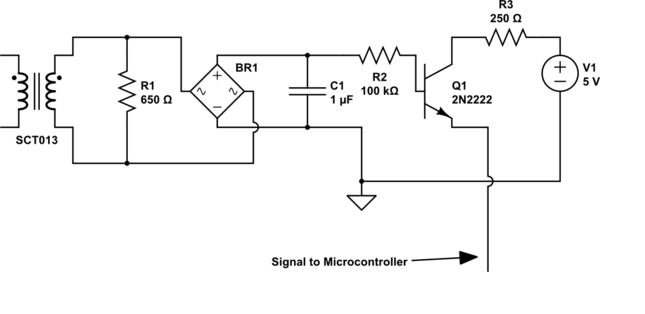
Something like this will work. Do not expose the ESP32 inputs to voltages higher than 3.3V, and be sure to connect the grounds.
If the AC current is ON, the output of the 2N2222 will be LOW.

Because your circuit only pulls the input up to 5V (which is too high anyway and will damage the input), there is nothing to pull it down to 0V.
I change the voltage to 3.3v and try the first digram with led works
I try your modification but it is not triggering the esp32 input
You may have destroyed the ESP32 input by exposing it to 5V.
I have button connected to the same gpio and it works
Then there is some other error in your circuit.
Post a clear, focused, closeup photo of your setup.
Use your multimeter to verify that the voltage at the 2N2222 collector changes when the AC current is switched on/off.
While trying i remove the resistor from colector and connect transistor collector to +3.3v direct and connect the gpio to collector also
It works i do not know how ??
I know it is not right but it works
After disassemble and assembling again your modificatiom works but the gpio vibrating between on and off for half second while the load is on
I draw the circuit power from esp32. 3.3v pin
The bridge rectifier BR1 is a poor choice for that circuit, because of the excessive voltage drop. Try using a single diode to rectify the CT signal.
See this study: YHDC SCT-013-000 Current Transformer — OpenEnergyMonitor 0.0.1 documentation
I remove bridge and put one diod instead but gpio stil vibrating on and off
Why not take a moment to provide some useful information in your posts?
For hints, see the "How to get the best out of this forum" post, linked at the head of every forum topic.
This photo for my circuit
And this video how it work
Esp32 code turn on the white led when input triggered and turn off green led
Can any one give a link or site about this issue as i google but not found what i am looking for
Hi,
Increase the value of the 1uF electro cap.
In the video it looks like you have changed your rectifier to a single diode.
Can we please have a circuit diagram?
An image of a hand drawn schematic will be fine, include ALL power supplies, component names and pin labels.
Thanks.. Tom.. 


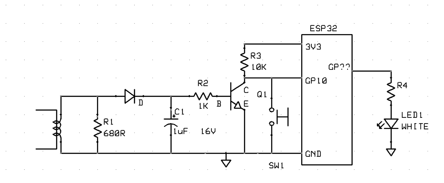
This is diagram
The esp32 powered from usb port connected to a power bank
The transistor powered from esp32 3.3v pin and grounded to gnd pin
Hi,
You might get better results with this configuration.
In your circuit the diode was the wrong way around.
The diode needs to be after the burden resistor.
To make the BJT conduct you must have the base of a NPN BJT positive with respect to the emitter to make the base-emitter junction forward biased.
Check your circuit. Especially the BJT pinout.
What is the part number of the BJT?
You will need to use your DMM to do some troubleshooting.
Tom..
I am using 2n2222
I modify the circuit as your digram and it works perfect on 4A AC load but less than 4A it not working
Hi, @amsteen
Instead of looping the current wire through the transformer once, try two or three times.
Tom..