Maybe print something in setup() or tag it with millis() so that you can make sure the issue isn't that the system is somehow resetting after each pulse.
I was playing with this in Wokwi with a button, (since I don't have your coil and Wokwi doesn't implement input capture) and find that your PWM works, and that cnt++ works.
volatile boolean PRINT = 0;
volatile boolean start = 0;
volatile unsigned int t1on = 0;
volatile byte cnt = 0;
volatile byte cnt1 = 0;
void setup () {
cli();//disable interrupts
Serial.begin(500000);//enalbel serial comunication
DDRD |= (1 << PD3) | //set pin 3 on port D as autput (bit manipualtion is faster then use digitalwrite,read or bitset )
(1 << PD4); //set pin 4 as output
DDRB |= (1 << PB1) | //UNO set pin 9 on port D as autput (bit manipualtion is faster then use digitalwrite,read or bitset )
(1 << PB2); //set pin D10 as output
DIDR1 |= (1 << AIN0D); // Disable Digital Inputs at AIN0 and AIN1(1 shift left to pin AIN0D - set AIN0D)
//ADCSRA &= ~(1<<ADEN);
//ADCSRB |= (1<<ACME); //Set ACME bit in ADCSRB to use external analog input at AIN1 -ve input
ADMUX = //referenc on AIN0 set to 2,5V
(1 << REFS1) | (1 << REFS0); //votage reference selection 00-Aref; 01-AVcc; 10-reserved; 11-1.1V (ARDUINO UNO-MEGA328p)
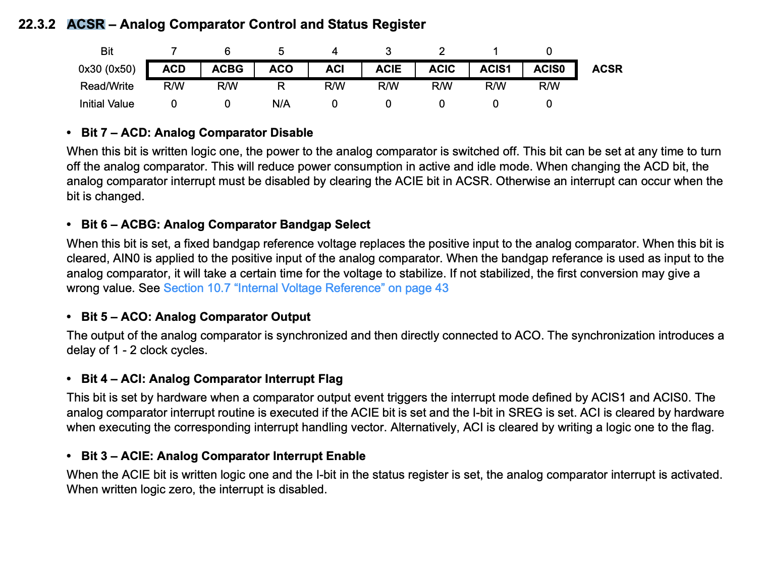
ACSR =
(0 << ACD) | // Analog Comparator: Enabled
(1 << ACBG) | // Clear ACBG to use external input to AIN0 +ve input
(1 << ACO) | // Analog Comparator Output: OFF
(1 << ACI) | // Analog Comparator Interrupt Flag: Clear Pending Interrupt by setting the bit
(1 << ACIE) | // Analog Comparator Interrupt: Disabled
(1 << ACIC) | // Analog Comparator Input Capture: 0-Disabled. Postavimo na 1 da omogočimo interrupt na timer 1, zajem stanja timerja v ICR1
(1 << ACIS1) | (0 << ACIS0); // Analog Comparator Interrupt Mode: 00-toggle, 01-reserved, 10-falling, 11-rising
TCCR1A =
(0 << COM1A1) | (0 << COM1A0) | // compare match mode COM1A 00-off, 01-toggle,10-clear on compare match, 11-set on compare match
(1 << COM1B1) | (0 << COM1B0) | // compare match mode COM1B 00-off, 01-toggle,10-clear on compare match, 11-set on compare match
(1 << WGM11) | (1 << WGM10); // select wawe generation mode - look on table in instraction
TCCR1B =
(0 << ICNC1) | // Input capture noice canlcler 1-enable
(1 << ICES1) | // Input capture edge select: 1-positiv edge select
(1 << WGM13) | (1 << WGM12) | // select wawe generation mode - look on table in instraction WGM13 1-non pwm mode
(0 << CS12) | (0 << CS11) | (1 << CS10); // cloclk select, 0- stoped, 1-prescaler 1, 10-prescaler 8...
OCR1A = 50000; //top VALUE max 65535 - PERIOD
OCR1B = 8000; //pwmB SETUP - PULS LENGHT
TIMSK1 =
(1 << ICIE1) | // Input capture INTERRUPT ENABLE
(0 << OCIE1B) | //Output capture B interrupt enable
(0 << OCIE1A) | //Output capture A interrupt enable
(0 << TOIE1); // cloclk select, 0- stoped, 1-prescaler 1, 10-prescaler 8...
sei();//enable interrupts
Serial.println("Starting...:");
pinMode(12, INPUT_PULLUP);
}
void loop()
{
if (PRINT == 1)
{
cli();
cnt1 = cnt;
uint16_t val = TCNT1;
uint16_t val2 = t1on;
PRINT = 0;
sei();
Serial.print(millis());
Serial.print(" ");
Serial.print(val);
Serial.print(" ");
Serial.print(val2);
Serial.print(" ");
Serial.println(cnt1);
}
//sei();
checkPin();
}
ISR(TIMER1_CAPT_vect)//pozor, za različne procesorje so lahko različni nazivi!
{
//cli();
t1on = ICR1;
++cnt;
PRINT = 1;
//sei();
}
void checkPin() {
static uint8_t last = 0;
uint8_t now = digitalRead(2);
if (now != last) {
last = now;
if (now == LOW) {
cli();
cnt++;
t1on = TCNT1;
PRINT=1;
sei();
}
}
}
I'd begin to suspect your circuit/wiring. Especially with
The PWM output and frequency should be hardware, and unaffected by printing, Maybe this means that something is interfering with the hardware? How much does the frequency not match 16000000/1/50000=320Hz?
Now the code is cleard and registeres are set with binary format of byte. For mi is that way a bit confusing to change desired bit. But every thing is working the same way. The value of ICR1 register is copied to variable t1on and shown on serial monitor. So I can observe inductive response of coil, when approaching with feromagnetic or aluminium material. I need increment of variable to manipulate result, averiging, use serial.println less intense and so on. Still I don't understand, whay is value of variable after each loop returned to zero. Is it possible, that some overflow makes soft reset, so the PWM is not interrupt. On osciloscope pwm signal is not interrupted.
//14.08.2024 Test interrupt Analog Comparator
//preverjeno delovanje interrupt analog comparator

//#include <avr/interrupt.h>


  volatile boolean PRINT=0;
  volatile boolean start=0;
  volatile unsigned int t1on=0;
  volatile byte cnt=0;
  volatile byte cnt1=0;

void setup () {
  Serial.begin(500000);//enalbel serial comunication
  cli();//disable interrupts
  //DDRD |=  (1<<PD3)|   //set pin 3 on port D as autput (bit manipualtion is faster then use digitalwrite,read or bitset  )
  //        (1<<PD4);   //set pin 4 as output
  //DDRB |=  (1<<PB1)|   //UNO set pin 9 on port D as autput (bit manipualtion is faster then use digitalwrite,read or bitset  )
  //        (1<<PB2);   //set pin D10 as output
  //DIDR1 |= (1<<AIN0D); // Disable Digital Inputs at AIN0 and AIN1(1 shift left to pin AIN0D - set AIN0D)
  pinMode(10,OUTPUT);//PWM(OC1A) on PD3
  //ADCSRA &= ~(1<<ADEN);
  //ADCSRB |= (1<<ACME);  //Set ACME bit in ADCSRB to use external analog input at AIN1 -ve input

  ADMUX = B11000000;
  //(1<<REFS1)  |   (1<<REFS0);   //b7,b6 votage reference on AIN0 selection 00-Aref; 01-AVcc; 10-reserved; 11-(mega 328p 1.1V,mega 8L 2.56V)

  ACSR = B01011110;       // Analog Comparator Control and Status Register
  //(0 << ACD)  |    //b7 Analog Comparator: 0 - Enabled hardware(1 - power save option to disable if not used)
  //(1 << ACBG) |    //b6 Analog Comparator Bandgap Select 1-enable internal refference connect to AIN0(+)
  //(0 << ACO)  |    //b5  Analog Comparator Output: 0-OFF, 1-ON to pin
  //(1 << ACI)  |    //b4 Analog Comparator Interrupt Flag: Clear Pending Interrupt by setting the bit
  //(1 << ACIE) |    //b3 Analog Comparator Interrupt: 0-Disabled, 1-enabled
  //(1 << ACIC) |    //b2 Analog Comparator Input Capture: 0-Disabled. Set to 1 to enable interrupt on timer 1, write current value of counter/timer 1 to ICR1 register
  //(1 << ACIS1) | (0 << ACIS0);   //b1,0 Analog Comparator Interrupt Mode: 00-toggle, 01-reserved, 10-falling, 11-rising

  TCCR1A =B00100011;  // Timer/Counter1 Control Register A
  //(0 << COM1A1)  |  (0 << COM1A0) |   // b7,6 compare match mode COM1A 00-off, 01-toggle,10-clear on compare match, 11-set on compare match
  //(1 << COM1B1)  |  (0 << COM1B0) |   // b5,4 compare match mode COM1B 00-off, 01-toggle,10-clear on compare match, 11-set on compare match
  //(1 << WGM11)   | (1 << WGM10);      // b1,0 select wawe generation mode - look on table in instraction

  TCCR1B =B01011001;  // Timer/Counter1 Control Register B
  //(0 << ICNC1)  |  //b7 Input capture noice canlcler 1-enable
  //(1 << ICES1)  |   //b6 Input capture edge select: 1-positiv edge select
  //(1 << WGM13)  |  (1 << WGM12) |   //b4,3 select wawe generation mode - look on table in instraction WGM13 1-non pwm mode
  //(0 << CS12)   | (0 << CS11)   |(1 << CS10);      //b2,1,0 cloclk select, 0- stoped, 1-prescaler 1, 10-prescaler 8...

  OCR1A=50000; //top VALUE max 65535 - PERIOD
  OCR1B=8000; //pwmB SETUP - PULS LENGHT

  TIMSK1 =B00100000;  // Timer/Counter1 Interrupt Mask Registe
  //(1 << ICIE1)  |   // Input capture INTERRUPT ENABLE
  //(0 << OCIE1B) |   // Output capture B interrupt enable
  //(0 << OCIE1A)  |  // Output capture A interrupt enable
  //(0 << TOIE1);     // Overflow interrupt enable

  sei();//enable interrupts
}

void loop()
{
  if (PRINT==1)
  {
    cli();
    cnt1 = cnt;
    PRINT=0;
    sei();
    Serial.println(t1on);
  }
  //sei();
}

ISR(TIMER1_CAPT_vect)//be careful, diferent processors can have different ISR name for the same function
{
  //cli();
  t1on=ICR1;
  ++cnt;
  PRINT=1;
  //sei();
}
It looks, that frequency is constantly 300Hz insted of 320Hz. If I use serial.println, than frequency start to oscilate a bit-few hertz, what can be seen on scope like occasional twitching of picture.
(300-320)/320=6.3% error. Larger than I'd expect for an Uno with a cheap ceramic oscillator. (it is an Uno, right?) I still think it might be resetting. Are you setting the right interrupt flags? If you've got something wrong there it won't call your ISR....
What about this one:
Don't you need an ISR(ANALOG_COMP_vect){...} for that?
For practical purposes, the only thing AVR Arduinos have running in background is the "millisecond" interrupt on Timer0.
The timers are also initialized for possible PWM use, but it looks to me like your Timer1 initialization is sufficient to override that.
Now the code is cleard and registeres are set with binary format of byte.
Your code with all the bits specified in gory detail was lovely; I wish everyone who initialized registers directly would do as well.
AFAIK (skimming the posts), the only complaint was about setting DDRx directly instead of using pinMode(), just from a point of clarity. Since the other features you're using aren't part of the Arduino IDE, there isn't much choice for using simpler functions there, and IMO your original code was fine.
I meant something like Serial.println("startup()..."); in startup(){...} so you could tell if it is repeatedly restarting.
Some sort of reset is sounding increasingly likely. What does your coil drive circuitry look like, and is is well-isolated from the AVR?
I don't think so. I think it is a hardware output independent of an interrupt vector. It's comparable to how the A and B outputs in pwm modes can be compare match hardware outputs and not based on compare match interrupts.
The comparator’s output can be set to trigger the Timer/Counter1 input capture function. In addition, the comparator can trigger a separate interrupt, exclusive to the analog comparator. The user can select interrupt triggering on comparator output rise, fall or toggle
Yes. For the direct hardware output without the need for the interrupt vector, I think it would be worth trying with the ACIC bit set, but not the ACIE bit.
Bit 3 – ACIE: Analog Comparator Interrupt Enable
When the ACIE bit is written logic one and the I-bit in the Status Register is set, the Analog Comparator
interrupt is activated. When written logic zero, the interrupt is disabled.
Bit 2 – ACIC: Analog Comparator Input Capture Enable
When written logic one, this bit enables the input capture function in Timer/Counter1 to be triggered by
the Analog Comparator. The comparator output is in this case directly connected to the input capture
front-end logic, making the comparator utilize the noise canceler and edge select features of the Timer/
Counter1 Input Capture interrupt. When written logic zero, no connection between the Analog
Comparator and the input capture function exists. To make the comparator trigger the Timer/Counter1
Input Capture interrupt, the ICIE1 bit in the Timer Interrupt Mask Register (TIMSK1) must be set.
Atmel ATmega328/P [DATASHEET]
Atmel-42735B-
Sorry for late respond, got ill bad. I have tested ACIE bit with zero and the intterupt rutine for comaparator is not needed any more. That is the best solution in my case. Thank you.