I plan to make a circuit where I would supply several groups of leds (each led consuming 20 mA).
There would be 13 groups of 2 to 4 leds, each group being controlled by a different pin of the arduino (power supply managed externally with a transistor). In each group, the leds would be connected in series.
So my question is to know if I can power each anode of each led directly to the ground plane of the PCB, while keeping an individual control of each led group.
If yes, I would like to know if the necessary current will be more than 20 mA per led group ? I would indeed like to know if by connecting each anode to the ground plane, we keep all the same the properties of a series connection (i.e. the voltages which add up and the current which remains fixed).
Thanks already to those who will take the time to answer
So my question is to know if I can power each anode of each led directly to the ground plane of the PCB, while keeping an individual control of each led group.
As best I can understand your description, and really I need to see a schematic, it makes sense apart from one very important detail: The anodes go to the positive supply not to ground (unless you are grounding the positive supply not the negative supply).
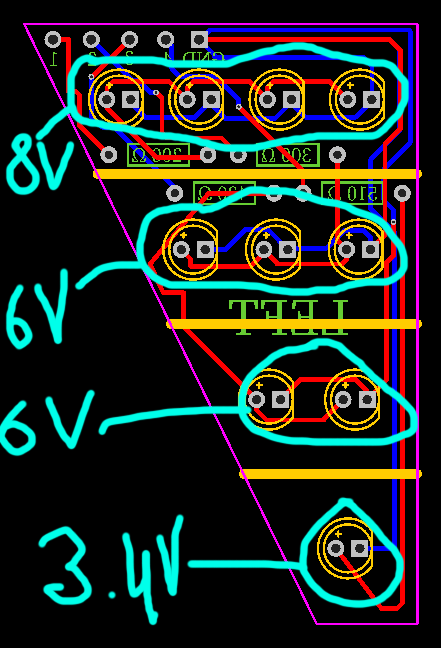
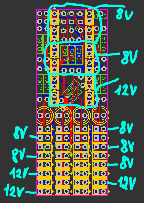
So here's the the first PCB schematic. I've circled each group and written the voltage needed. I still haven't put a ground plane because I don't know if it's a good idea.
At first glance those LEDs look like they're in parallel not series...but a proper schematic should make it clear.
If the LEDs in a group are in series then obviously you CANNOT connect all of either the anodes or cathodes to the same place. That makes no sense at all.
You need to have a MOSFET between the cathodes and ground and connect the supply voltage to the anodes, with a resistor in between somewhere. You don't need lots of different voltages, you need one voltage high enough for all the LED strings and different resistors to get the right current.
Please provide a schematic, not a PCB layout. Maybe the software you are using is different to the KiCAD, which I use, but in KiCAD you can't produce a PCB layout without producing a schematic first.
slipstick:
If the LEDs in a group are in series then obviously you CANNOT connect all of either the anodes or cathodes to the same place. That makes no sense at all.
Well, I thought it could work (even if I'm not sure, that's why I'm asking it here ) because it is always possible to control independently leds that are connected to the same ground but are connected to different arduino pins.
PerryBebbington:
You need to have a MOSFET between the cathodes and ground.
Why should I do that ? (it's not that I don't believe you, but I just want to understand haha)
PerryBebbington:
You don't need lots of different voltages, you need one voltage high enough for all the LED strings and different resistors to get the right current.
In fact, I plan to use a LiPo battery (14.8V) to supply power to all the circuit, which I'll then regulate with a LM317. I'll also use transistors to "link" supply power with arduino pins. If I'm showing different voltages for each leds group is because there aren't the same number of leds in each group or because the led color is different from the others (and so, they need a different voltage). However, I don't know if I was wrong to make my calculations like that, as that's one of my first design .
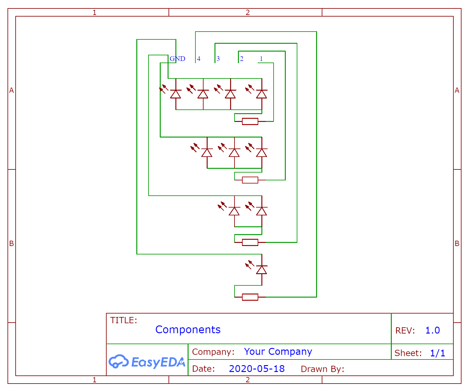
So here's the schematic. I precise that I've routed the cathodes but what I'd really like is to connect all of them to a ground plane (if that's possible, obviously)
Just to be clear - what you want to do is just to switch GROUPS of LEDS on and off.? Not individual LEDs and not any dimming etc. Just on/off. Is that right.
Anyway what you have so far is parallel connection and connected that way the voltages DO NOT add up but the current does. So a group of 4 would take 80mA and that's way too much for a digital pin. So you would need MOSFETs. And even if you do connect in parallel like that then you still need a series resistor for EACH LED not one for a group.
If you connect in series (Cathode of one LED to Anode of the next and so on) then the voltage adds up, current stays same and one resistor per group will work. But then you'll need more voltage then you can get from a digital pin so you'll need MOSFETs again and this time high voltage source.
It's probably a good idea to learn a bit more about what parallel and series actually mean and how that works out for LEDs before you go any further with this project.
Oh sorry, I just realized I've made a big mistake. I knew how the principle of series and parallel connections worked, but I didn't know that the anodes had to be connected to the cathodes for series connections... It's obvious to me now :o
So yes, what I want to do is to be able to just turn on or off each group of leds independently. That's why I planned to use a "high voltage" battery (14.8V) with transistors to power the groups with simple arduino pins. (Tell if I'm wrong but I'd gathered the transistors might be better suited for that kind of circuit than MOSFETs)
So my question is if, despite the different voltages needed for each group, can we still connect all the cathodes at the end of each group to the same ground plane?
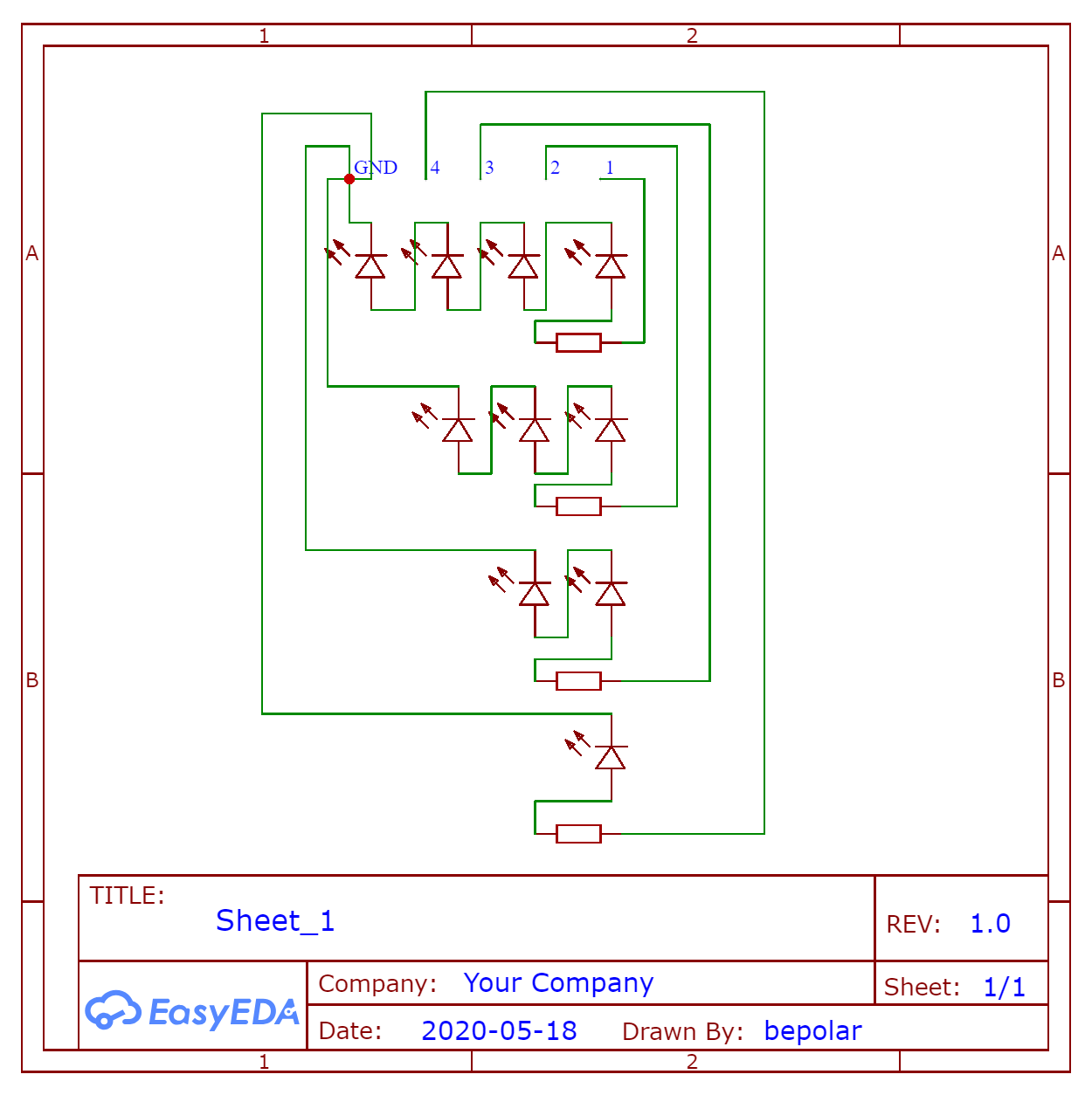
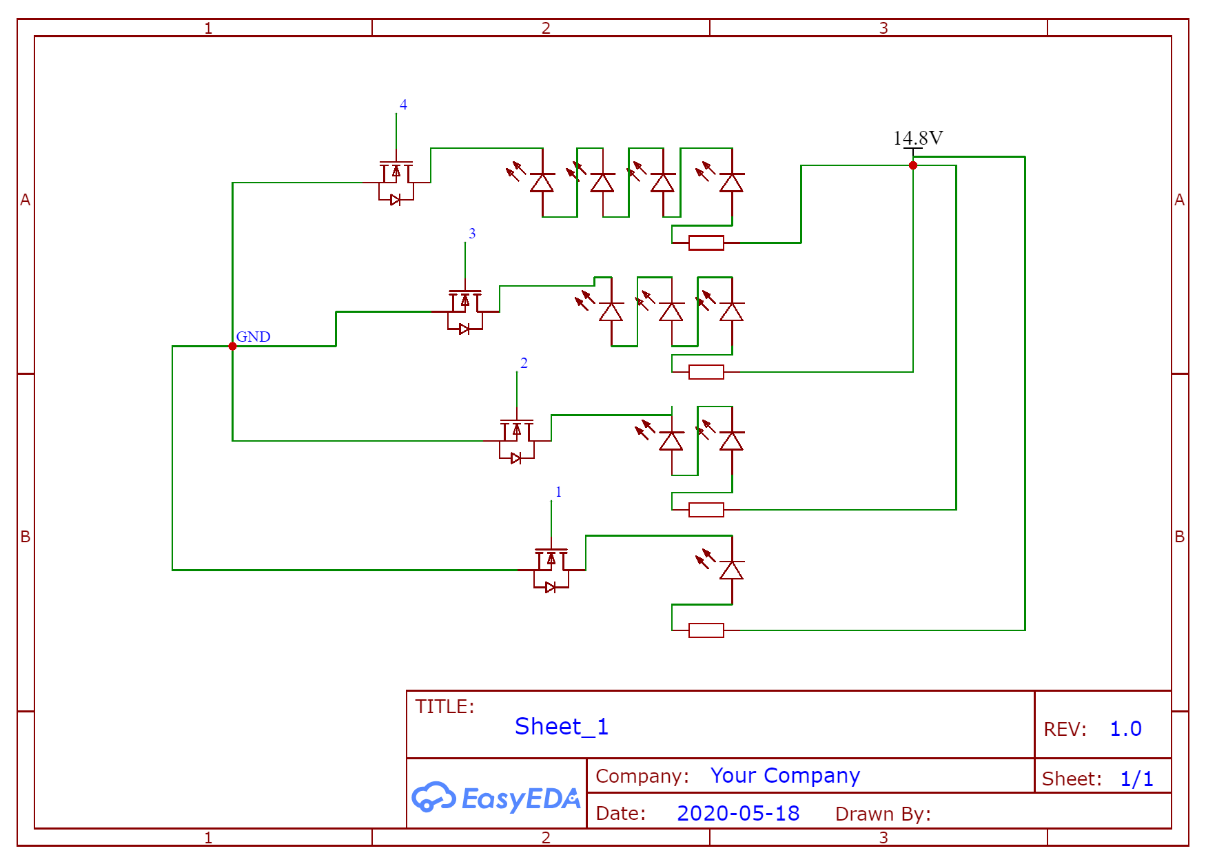
Here is also the new schematic that should be correct (don't hesitate to confirm me if it is correct now , always knowing that even if I have already routed everything on the schematic, I would still like the ground routing to be done from the ground plane, if possible)
So my question is if, despite the different voltages needed for each group, can we still connect all the cathodes at the end of each group to the same ground plane?
Yes, but as I might have mentioned before, it's better if you put the transistor between ground and the cathode of the bottom transistor and connect the anodes to the positive supply via their resistors.
Tell if I'm wrong but I'd gathered the transistors might be better suited for that kind of circuit than MOSFETs
You're wrong. Use an N channel MOSFET wired as I suggested above.
Bipolar junction transistors are last century's technology, MOSFETs are much better. You put them in the ground circuit because they are easier to control that way.
PerryBebbington:
And you of course know the series resistor gets smaller in value as you add a LED to a string.
Yes I do but thank you for the reminder !
PerryBebbington:
Bipolar junction transistors are last century's technology, MOSFETs are much better. You put them in the ground circuit because they are easier to control that way.
Ok, so does that mean that $ that I can connect the last cathode of each group to the same ground plane, even if each group needs different voltages ?
I think it's time you produced a new schematic taking into account the advice you have been given and show us what you have. I am finding it difficult to know what you have understood or misunderstood and a new schematic will clearly show if you are on the right track or not.
larryd:
Actually, suggest you wire as common anodes.
I'm not sure I understand what you meant by common anodes. I took a close to look at the schematics you've shared but when I googled the term 'common anodes', I saw that this technique was used for 7 segment displays and that kind of stuff, so I don't understand what this kind of wiring could bring to the schematic?
Also, would that be possible to wire the mosfets as a high side switch. I know that it's what you've done on the schematics you've shared but I've been recently told that we could'nt do that (at least with BJT) but I don't know if it's true.