I am brand new to hobby electronics and have been studying for the past two days straight and thought I had nailed the basics.....
This is literally my first time trying to put theory into practice and I took a positive feed from the 5v pin and a negative / ground from the ground pin beside the 5v pin on the Arduino and ran them via solid core jumper to my breadboard. I measured the voltage using my multimeter and it's near enough 5v so everything ok so far.
As I was wanting to practice reducing current and voltage I placed a 1k resistor on the positive line and tested the voltage again using the multimeter expecting a drop of some sort and it was exactly the same. I then tested the current from the directly via the Arduino which was 0.20 on multimeter and again after the resistor and again it's exactly the same. I then added a 200ohms resistor in addition to the 1k but again all readings are the same.
I know what you are thinking I have wired everything up wrong and bypassing the resistors in some way but I literally checked four times and everything is as should be.
Is there some sort of strange Arduino issue with using it as a power supply for testing straight from the 5v pin because I cannot understand what else could be wrong I mean surely there should be some drop in both measurements??
I would really appreciate any help and please understand I really am a beginner so if you could be as direct / detailed as possible it would be great.
As I said I am an absolute beginner so plan drawing is still a little bit in the future. With all due respect I don't see the need for a plan when it's simply a live wire connected to the 5v pin with a 1k resistor on it. All values were stated being 5v, 1k ohms resistor and then a 2nd resistor at 200 ohms so not a lot to put into a diagram. Multimeter reads 5v with and without resistor and 0.20mA again with and without resistor.
I suppose I should have expected a reply like this and therefore did hesitate posting at all as with forums the world over there is always someone in the "community" to take the time to reply to tell the beginner that his question was wrong instead of an attempt to help.
Ok
So you have +5----1k-----200-----0v
From where to where are you measuring 5 volts?
When you measure the current, is the meter in series with the two resistors?
Is your meter set to the amps range when measuring current? What setting, 20mA?
From your description, it is not clear when you are using the meter in Voltage mode and when you have it in series with the parts to measure current. Hence, the request.
Now you've added an LED, so that is new.
0.2mA is awfully low.
With 5V and LED Vf of say 2.2V for Red, with 1K resistor I'd expect:
(5V - 2.2V)/1000 = 2.8mA
With 200 ohm, even more current:
(5V -2.2V)/200 = 14mA.
So if you seeing 0.2A, 200mA, so thing is not right.
From your story I gather that you have connected a 1K resistor to 5volt, left the other end unconnected, and tested the voltage at both ends.
You would have seen 5volts at both ends.
Imagine a long garden hose, connected to a tap with a certain water pressure (volts).
That pressure will be the same at the tap end and at the nozzle end.
belfastrab:
I suppose I should have expected a reply like this
Cliches are cliches for a reason, and a picture does indeed replace a thousand words. You should make it a priority to be able to read and draw simple circuits. A quick pencil diagram and photo uploaded from your phone is adequate. It reduces the guesswork.... if there's confusion about such a simple circuit (or not-a-circuit if there's no closure 8) ) in words, imagine when you get to multiple components, and ICs with a dozen or more pins.
What's confusing from your description, was that it wasn't clear if the "other" end of the resistor (ie the one not on the 5V) was connected to the Gnd or left loose. It seems the latter, but I'm still not 100% sure.
If loose, then as Wawa says, you will get 5V on both ends of the resistor, since there's no circuit and hence no current.
You may find my replies in this thread useful, particularly #14
Thanks for all the replies. I think I have figured out what the problem was.
It seems that the location of the resistor on the breadboard for whatever reason needs to cross the little divide in the middle if it's placed "bridging" this divide then it works as it should. However if it is placed on the same line but not bridging the divide then it doesn't work at all.
I scraped the previous set up and created a simple test still remembering I am brand new to this so please forgive me if I am saying stuff wrong.
The new test runs 5v positive using solid core jumper to the top of the breadboard onto the positive row / rail and a negative / ground jumper to the bottom of the breadboard.
In the middle of the breadboard I placed a 1k ohms resistor bridging the gap / grove/ divide and ran the positive feed through it and on to the anode leg of the LED. The cathode leg of the LED was connected to the negative row / rail completing the circuit.
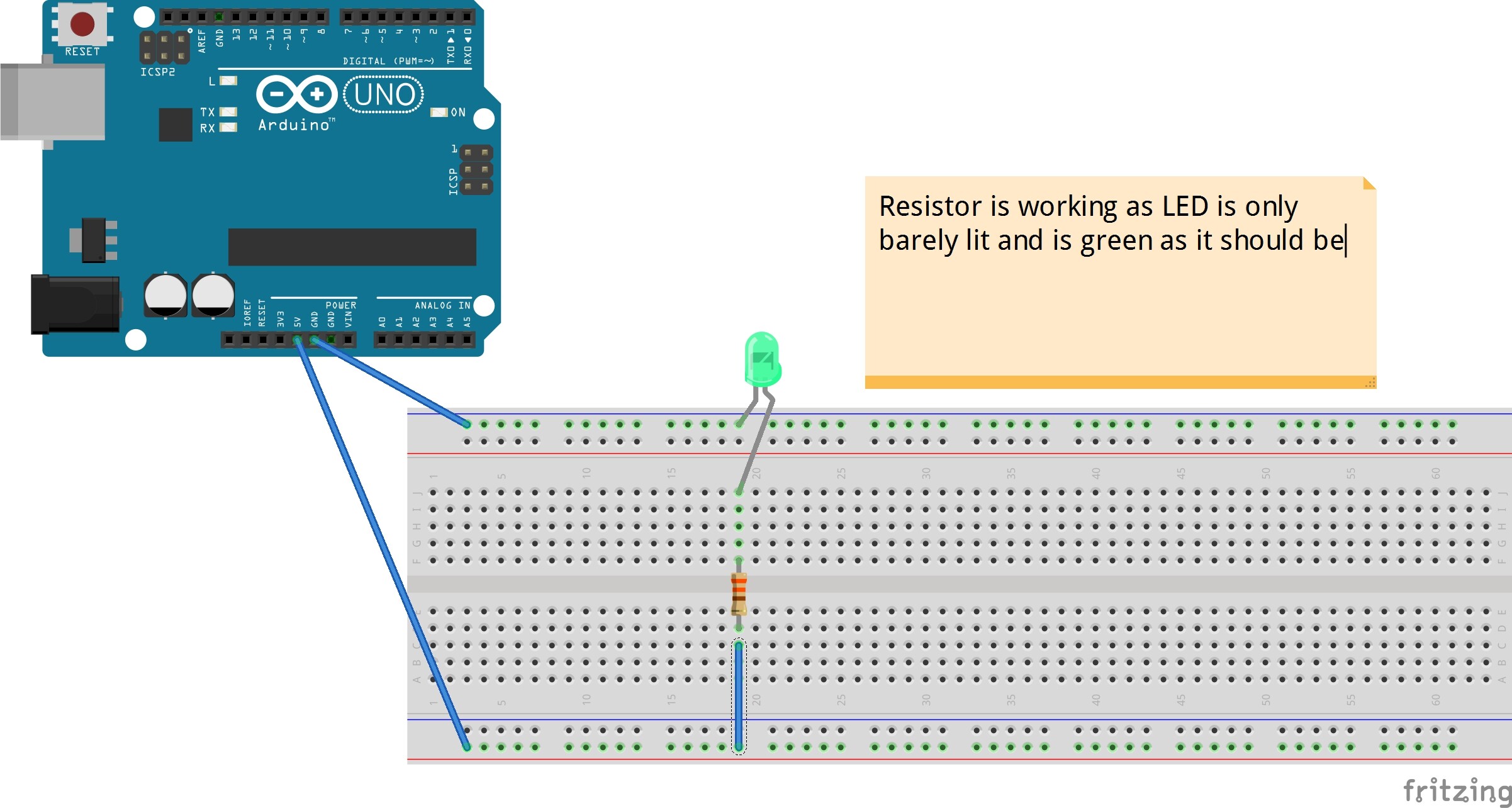
All works as it should because of the high resistance from the resistor the LED barely lights and is green as it should be. So without using a multimeter I know and can see the resistor is clearly working.
However if I move the resistor so it's still on the same line / row as it was but no longer bridging the gap the LED goes super bright and turns yellow which means that the resistor is no longer working which I can't figure out why because I know there is definitely current flowing through it given the extreme reaction of the LED.
As suggested I have looked into drawing diagrams and I also vaguely remember reading somewhere on these forums that Fritzing is not liked very much so I hope no one minds but to help explain what I mean above I have created two diagrams / pictures using Fritzing.
The images diagrams shows the resistor "bridging" and working and the other shows it not bridging and therefore not working.
So my question would be why given the resistor has current flowing through it does it not work unless it's bridging this middle divide / gap / grove?
Sorry if this post is all over the place and long.
All the 5 dots where your resistor is in the non-working one, are connected together.
So effectively, the blue vertical wire is actually connected direct to the led's leg, and the resistor has a "wire underneath it" so to speak, inside the breadboard.
Ahhhhh.... I see so thanks to this wire underneith I am bypassing the resistor hence the LED getting hit with the full force of the voltage and current from the 5v supply.
Thank you that makes it a whole lot clearer now. Sorry to be a pain but can you please confirm what I have said in this post about bypassing is correct.
Never mind I tested it myself a few different ways and confirmed what you said (not that it was ever in doubt) and answered my own question. I just wanted to make sure I had understood correctly what you meant.
I then thought oh so resistors all need to be mounted across this middle divide / gap but I actually applied what little intelligence I have and turned the resistor 90 degrees and mounted it sideways to avoid the under bypass issue.
Hi - great rookie mistake! Had much fun reading this topic and trying to figure out what your problem was. Most people would probably not have guessed this because they know the inner workings of a breadboard.
I am also a beginner even though I have been playing with Arduino's for a couple of years now. I visit them every now and then as side projects and I use them for home automation projects. I've been a software guy my entire life and thanks to Arduino I became interested in hardware and programming hardware. It's a great hobby.
I have small tip: use the beep mode on your multimeter to 'debug' or troubleshoot your circuits. I use it a lot to check and double check and triple check (I have fried quite some stuff :D).
Welcome to the 'community' (wink) and have a good day!
Good luck on future projects!