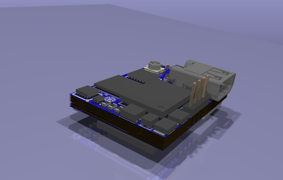
I have been working on this rather small (20x14mm) stm32 pcb, based on the stm32 In 5x5mm package. It has a mipi to hdmi converter, Murata wifi chip, small debug connector, 256mb flash and 64mb ram. It also has USB HS lanes ready to be brought up from bottom, USB FS from top, and can FD and few IO pins going to the right, but the design is partially modular, to allow custom arrangements of these pins. There is also a reset and boot select button. Sadly my firmware development skills mean Ill probably never get this manufactured, but it would be a fun pcb to make, basically kind of like a mini portenta.
What software did you use to do this? That looks great!
1 Like
I used KiCad, and rendered it with raytracing. Most 3d models I just found on Component search engine, apart from Murata wifi I quickly made in fusion. Here is a picture of the pcb, but its 8 layers and blind vias so a bit of a mess.

I probably couldn't... That looks complicated! But why did you design it if you're not going to develop it? Or are you looking for some here to program it, etc?
1 Like
I certainly would want to develop it at some points, if my programming skills ever get to that point, though if enough people found it interesting, would be cool if someone else helped too. But partially it was just to spend time, and try making an 8 layer pcb for the first time. I also have to wait for JLC to start offering blind vias, to which they said soon, so I can get this manufactured for not a totally crazy price.
no mounting holes?
Not by default, but adding a usb port, could add them next to it, and if you add one to top one to bottom, that’s space for enough. I can look into including some, but due to density, mounting holes will probably need to be part of the I/O extensions
This topic was automatically closed 180 days after the last reply. New replies are no longer allowed.