I am doing a project which is currently working pretty good on my breadboard and I would like to order a PCB online. My problem is that I am using an ESP32 dev board (where I just plug the usb cable and program the ESP32 and the 3.3V is also provided) and a relay module.
When designing the PCB instead I am using just the ESP32 module (without the USB adapter) and I will design the relay module and the 3.3V step down myself.
I would like to double check with anyone of you that will be kind to assist if the design of these modules are correct.
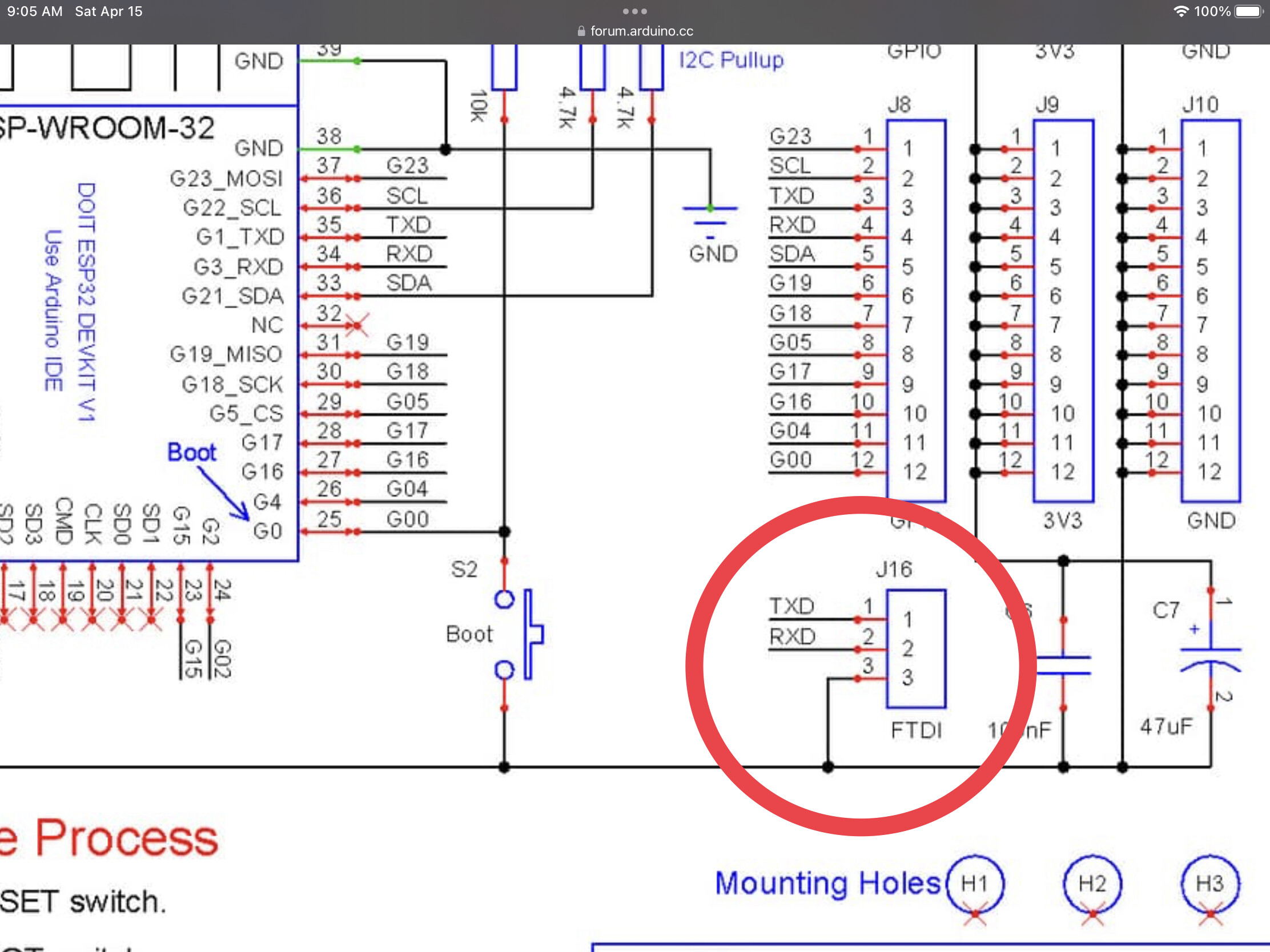
The first is the ESP32 module. I need to program it while it is on the board using an FTDI serial adapter and I also have provided the reset and boot buttons:
The second is the 5V to 3.3V converter:
And the last one is the relay module with optoisolator:
Thanks for the schematic, that's very useful.
I am going to order the PCB already assembled online, no idea indeed how to solder a chip like that or any SMD component.
Well the best approach is to actually get one of them first, solder it onto a breadboard adapter (just a bit of prototype board and some pins will do) and test that out as well.
depending on the package that you intend to use, and a bit regardless of that, you will have to observe the size of the heatsink. An ESP32 is rated for 250mA, and i think that the onboard LM1117 on a dev board uses a lot of the PCB as a heatsink (also because the claims that it can provide the full 600mA when stepping down from 5v)
Pretty sure you can test that already. I would use a 1N4148 as a fly-back (not a 1N4007) and increase the value of R2, although i am not familiar with the 2n3904, but looking at the datasheet i see it only comes in THT package, and i guess i would find a part that comes in SMT package for a PCB design instead.
Hmm yeah the pins are significantly pitched smaller than a barebones ESP8266,
That will mean that you will be at the mercy of the PCB manufacturing company. You should make sure that what you have designed will actually work before you get them to put it together.
How about you design a barebones ESP32 onto a breadboard-friendly PCB first.
Oh yes and if you don't, remember the 'keep-out' zone of the antenna.
Thanks for responding. Indeed probably a good option would be to create a board with just the ESP32, the LM1117 and the programming pins in order to test it.
Yep, but given how close those parts are it wouldn't have hurt to just connect them in the schematic.
as said, i think i will include a 'barebones ESP32 with just all the pins connected to male (or even female) header pins. Take the rest completely off the table.
Hi, @sergiocap
Is there a reason why you don't use the ESP32 dev and place header socket on your PCB to plug it into.
So more than halving your PCB complexity.
This is an example during protoboarding I did with a Nano.
Well then the ESP family really comes into it's own with OTA updates.
I like the way you have added glue to the screwterminals it took me a while to get to that. Usually the pins are to big for the board, and the solder does tend to breeak.