I wrote some test code to make a vex motor move using an Arduino. I wrote this code to try to get a better understand on how to make a vex motor work in Arduino. I uploaded to code to my Arduino but nothing happens I'm not sure what the issue might be, I think the code is good but I'm not sure. Also do I a battery or is the computer enough
Please post an annotated schematic and links to technical information on the hardware devices. Frizzys do not work for me. You also need to follow the forum guidelines on posting your code. It also helps to comment the code.
Please post a link to the product page or data sheet for this motor, and the details of the motor power supply. Why do you think it acts like a hobby servo?
The Vex 393 is just a motor, and requires a motor controller, a separate motor power supply, and code that is appropriate for whatever motor controller you choose.
Do not try to use the Arduino 5V output to power motors or servos, and avoid any tutorials that suggest it is OK to do so (there are lots of them, and they are all wrong).
I plugged it into vin and I'm using an external power supply but it still wont run when I do upload.
Also what do you mean add code tags. Im not sure what that is..
Code tags are devices which will make your code appear in a selectable box like this which make it easy for others to copy and run your code.
type or paste code here
There is an automatic function for doing this in the Arduino-IDE
just three steps
1)press Ctrl-T for autoformatting your code
2)do a rightclick with the mouse and choose "copy for forum"
3)paste clipboard into write-window of a posting
Also clicking on the </> icon in the header to a post will produce the box to place the code.
from the link you shared, there are 2 versions of that motor and I'm guessing you have the 3-wire version which should work with the Servo library, based on the info given:
3-Wire Servo
Rotation: 100 degrees
Stall Torque: 6.5 in-lbs
Voltage: 4.4 - 9.1 Volts (Motor life will be reduced operating outside this range)
PWM Input: 1ms - 2ms will give full reverse to full forward, 1.5ms is neutral
Black Wire: Ground
Orange Wire: Power
White Wire: PWM signal
Current Draw: 20mA to 1.5 A per Servo
Max Power: 4.9 W when rated @ 6V
assuming you have wired everything correctly, you should also be able to test your motor/servo with this code:
/*the sg90 accepts 3 command pulse width
  1ms - CCW movement
  1.5ms - return to center position
  2ms - CW movement
  minimum time between pulses/steps - 20ms

  This example used delay() to demonstrate servo operation.

*/

uint8_t DirectionInputPin = 9; //change this to the ACTUAL pin being used!!!
uint8_t sg90ControlPin = 8; //white wire - change this to the ACTUAL pin being used!!!

uint8_t CCWpulseWidth = 1;  // milliseconds
uint8_t CWpulseWidth = 2;  // milliseconds
int millisbetweenSteps = 20; // milliseconds - or try larger values for slower steps

uint8_t numberOfSteps = 100;
uint8_t dir_req;

void move_servo(int Steps, uint8_t pulseWidth) {
  for (uint8_t n = 0; n < Steps; n++) {
    digitalWrite(sg90ControlPin, LOW);
    delay(millisbetweenSteps);
    digitalWrite(sg90ControlPin, HIGH);
    delay(pulseWidth);
  }
}

void setup() {

  Serial.begin(115200);

  pinMode(sg90ControlPin, OUTPUT);
  digitalWrite(sg90ControlPin, HIGH); //reduces chances of jitter on powerup/reset
  //a 1k pullup resistor between sg90ControlPin and VCC would also help

  pinMode(DirectionInputPin, INPUT_PULLUP);

  //initialise direction flag
  dir_req = digitalRead(DirectionInputPin);

  Serial.println("Starting Sg90 Demo");

  //abitrary delay
  delay(2000);

  //servo initialisation
  //move servo to center positon
  digitalWrite(sg90ControlPin, LOW);
  delay(20);
  digitalWrite(sg90ControlPin, HIGH);
  delayMicroseconds(1500);
  digitalWrite(sg90ControlPin, LOW);
  delay(20);
  //move servo fully CounterClockwise (approximately 90 steps)
  move_servo(90, CCWpulseWidth);

  //abitrary delay
  delay(2000);
}

void loop() {

  if (digitalRead(DirectionInputPin) != dir_req) {

    dir_req = digitalRead(DirectionInputPin);

    //move servo Clockwise
    if (dir_req == HIGH) {
      move_servo(numberOfSteps, CWpulseWidth);
    }
    //move servo Counter-Clockwise
    else {
      move_servo(numberOfSteps, CCWpulseWidth);
    }

  }

  delay(millisbetweenSteps);
}
Also I would advise to power your motor/servo directly and not from your arduino board.
If you have the two-wire-version it will work definitely not with the servo-library.
This motor looks like a servo but the two wire-version is not a servo
This company is bad on documentation. at first glance the website looks like explaining all things but it doesn't.
The two wire-version must be driven not with the servo-library but with function analogWrite()
void setup() {
// DON'T touch the pin you are giving to the Servo library
// to control.
//// Remove:  pinMode(MotorPin, OUTPUT);
  motorControl.attach(MotorPin);
}

void loop() {
// DON'T touch the pin you are giving to the Servo library
// to control.
//// Remove:  digitalWrite(MotorPin, HIGH);

// This is declaring a local variable with the same name
// as your function.  It does not call your function.
int motorControl(100);
delay(5000);
}
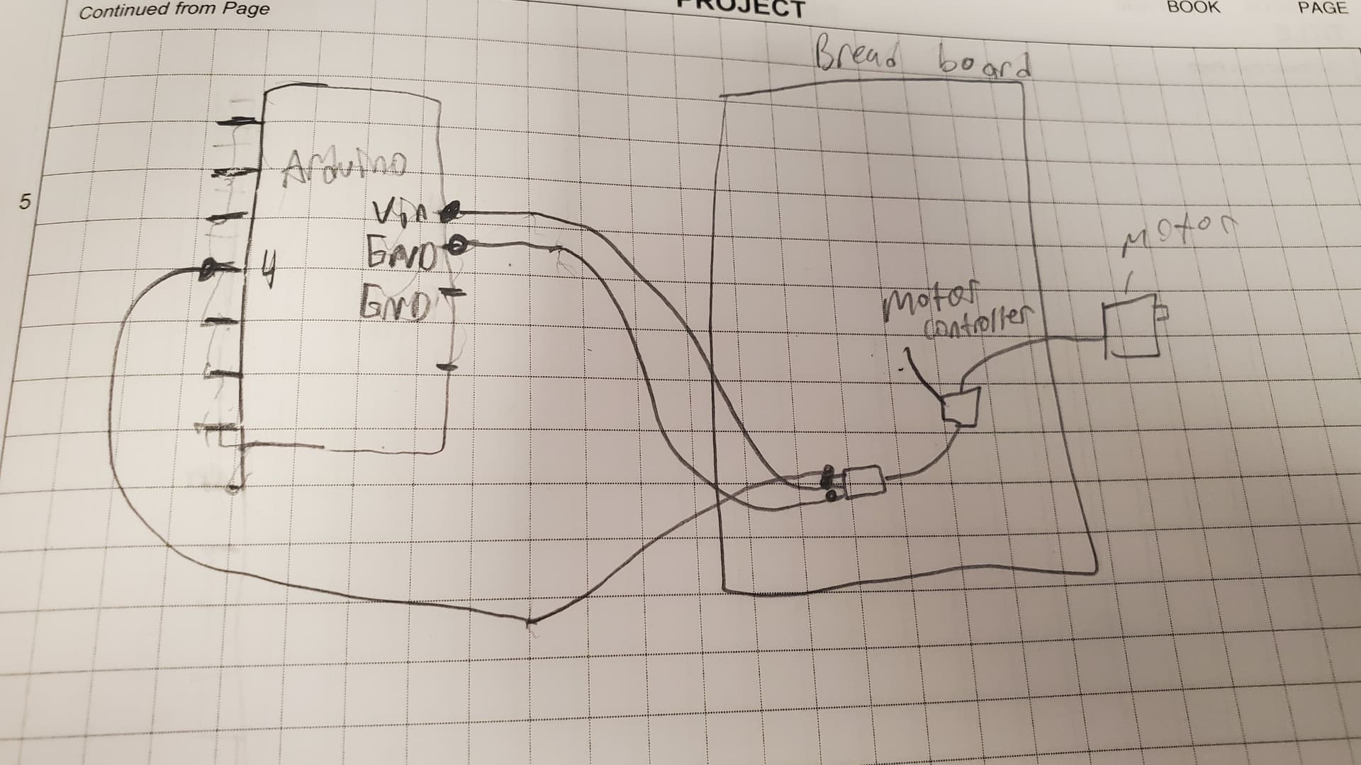
the vex motor I'm using has two pins but it goes into a motor controller which has three pins. The motor controller part is wired up to the Arduino. Does this change the code at all and is the vex motor considered as a motor or a servo in Arduino .
It seems clear that a two wire motor (usual simple DC motor number of wires) is being controlled by something that uses 3 wires to the controlling microprocessor (usual number of wires for a servo).
So it's a servo from the code point of view.
Now you may have a servo that goes from 0 to 180 degrees as the servo pulse goes from 1 to 2 ms or…
… you may have a continuous rotation servo that goes CW if the pulses are shorter than 1.5 ms, faster the more so, and CCW if the pulses are longer than 1.5, again faster the more so.
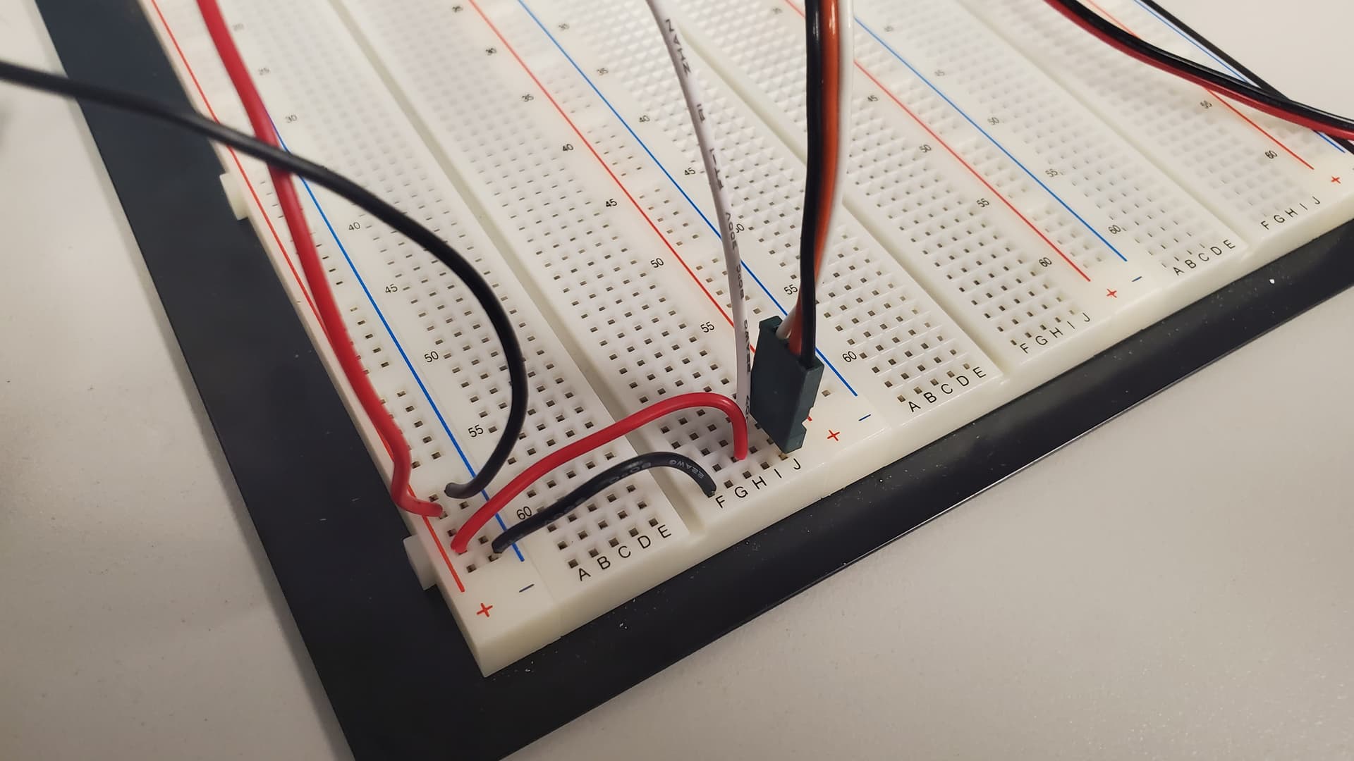
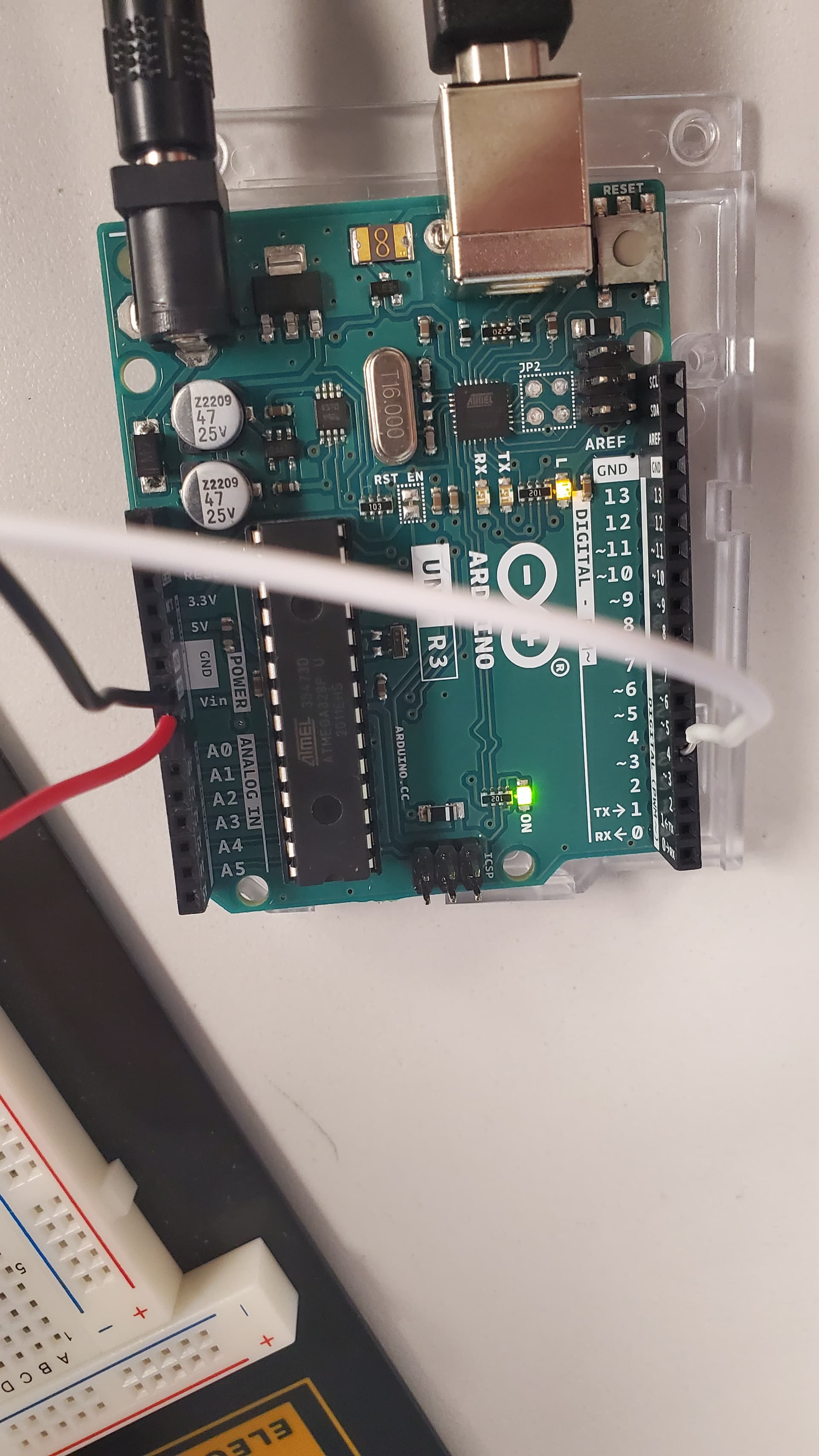
Ok thank you. I've been try all the sketches that were suggested to me here but when I press upload the motor still wont move. I think maybe its a wiring issue but I'm not sure. Is there a different forum that can help me troubleshoot my wiring.
You can, but a hand drawn schematic in addition would be the best.
Just draw all the parts and all the wires and make sure to show where power is being provided and by what.
If you've never drawn a schematic, google
electronic schematic basics
pick "images" and poke around a bit.
It's very simple and again, pencil and paper and your cellphone is all you need, and is often the best, as you need to know how to do it by hand if you ever get around to using CAD schematic drawing, as it will not think for you anyways. A distraction you don't need here.