Im trying to run a Nema 17 stepper motor with the driver board Polulu DRV8825, but the stepper is vibrating and makes a squeaky sound for a few sec and then it stops.
I've tried to make a paint-image to show my schematics:
// testing a stepper motor with a Pololu A4988 driver board or equivalent
// on an Uno the onboard led will flash with each step
// this version uses delay() to manage timing

byte directionPin = 9;
byte stepPin = 8;
int numberOfSteps = 100;
byte ledPin = 13;
int pulseWidthMicros = 20;  // microseconds
int millisbetweenSteps = 25; // milliseconds


void setup() {

  Serial.begin(9600);
  Serial.println("Starting StepperTest");
  digitalWrite(ledPin, LOW);

  delay(2000);

  pinMode(directionPin, OUTPUT);
  pinMode(stepPin, OUTPUT);
  pinMode(ledPin, OUTPUT);


  digitalWrite(directionPin, HIGH);
  for(int n = 0; n < numberOfSteps; n++) {
    digitalWrite(stepPin, HIGH);
    delayMicroseconds(pulseWidthMicros); // this line is probably unnecessary
    digitalWrite(stepPin, LOW);

    delay(millisbetweenSteps);

    digitalWrite(ledPin, !digitalRead(ledPin));
  }

  delay(3000);


  digitalWrite(directionPin, LOW);
  for(int n = 0; n < numberOfSteps; n++) {
    digitalWrite(stepPin, HIGH);
    // delayMicroseconds(pulseWidthMicros); // probably not needed
    digitalWrite(stepPin, LOW);

    delay(millisbetweenSteps);

    digitalWrite(ledPin, !digitalRead(ledPin));
  }
}

void loop() {
}
Any ideas of whats going on?
Ive set the potentiometer to 0.8V to get 1.6A, using multimeter from GND to the top of potentiometer.
The Pololu DRV8825 web page has a good wiring diagram. I don't see a large capacitor in your picture.
Sorry, I can't make sense of the wiring in your photos. Just make a simple pencil drawing and post a photo of that.
The Pololu page also explains how to set the current limit. There is a special reference point on their boards for measuring the voltage. If your board is different please post a link to its datasheet.
Also, post a link to the datasheet for your motor. There are hundreds of different Nema 17 sized motors.
It doesn't matter how the wires are connected, as long as the two A and two B connections are made. To pair As and Bs, check for continuity with a multimeter. While you are at it, measure the winding resistance and tell us what it is.
If the direction of rotation is wrong, reverse the connections on one of the A or B pair.
You can find out the pairs of your motor without measuring:
disconnect the motor from driver
turn the shaft - it will go without too much resistance
now connect one pair of wires (let's say red and green) and repeat turning the shaft
3a. if there is same kind of resistance like before (in 2.) - keep the one wire in your hand and connect it with another wire (the white one or the black one)
3b. turn the shaft - if there is a bigger resistance you got one pair which belongs to one coil
the remaining two wires are connected with the second coil of the motor
These are pretty good values for a NEMA17 stepper.
I would suggest, use the Accelstepper library to test your stepper as this library is easy to use (you will find a lot of information in this forum where people used this library);
The library takes care of more than one stepper, comes with acceleration, for a dir/step driver just use the declaration like so:
#include <AccelStepper.h>
AccelStepper stepper1(1, 3, 4);  // Define stepper and the pins we will use
This tells the library to use a "step/dir controlled" driver like the drv8825.
Have a look at the examples which come with the library.
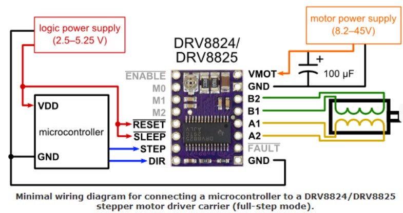
You have to make sure that you wire your drv8825 as follows:
Hi, Imfao.
It is mandatory to have a capacitor in your circuit that is wired to both Vin and GND terminals. I had the same problem with this DRV8825 driver (stepper produced squeaky sound, but did not rotate) until I added a capacitor as rpt007 showed with the hook-up diagram.
Just in case, here a nice guide for adjusting the potentiometer, where you can see the wiring of the driver to the microcontroller.
And also some explanation for the necessity of a capacitor (from http://www.instructables.com/id/Stepper-Motor-Module/?ALLSTEPS):
" If you like the electricity-as-water analogies - your motor going on and off and moving is going to create a lot of waves and the capacitors act as mini-flood planes to help smooth out the flow. 10 uF for the motor side. 1 uF for the logic side."