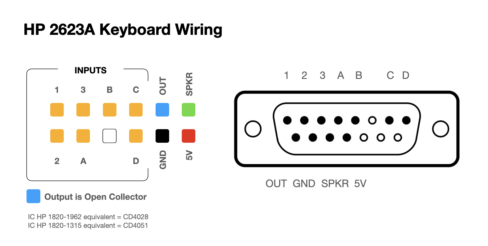
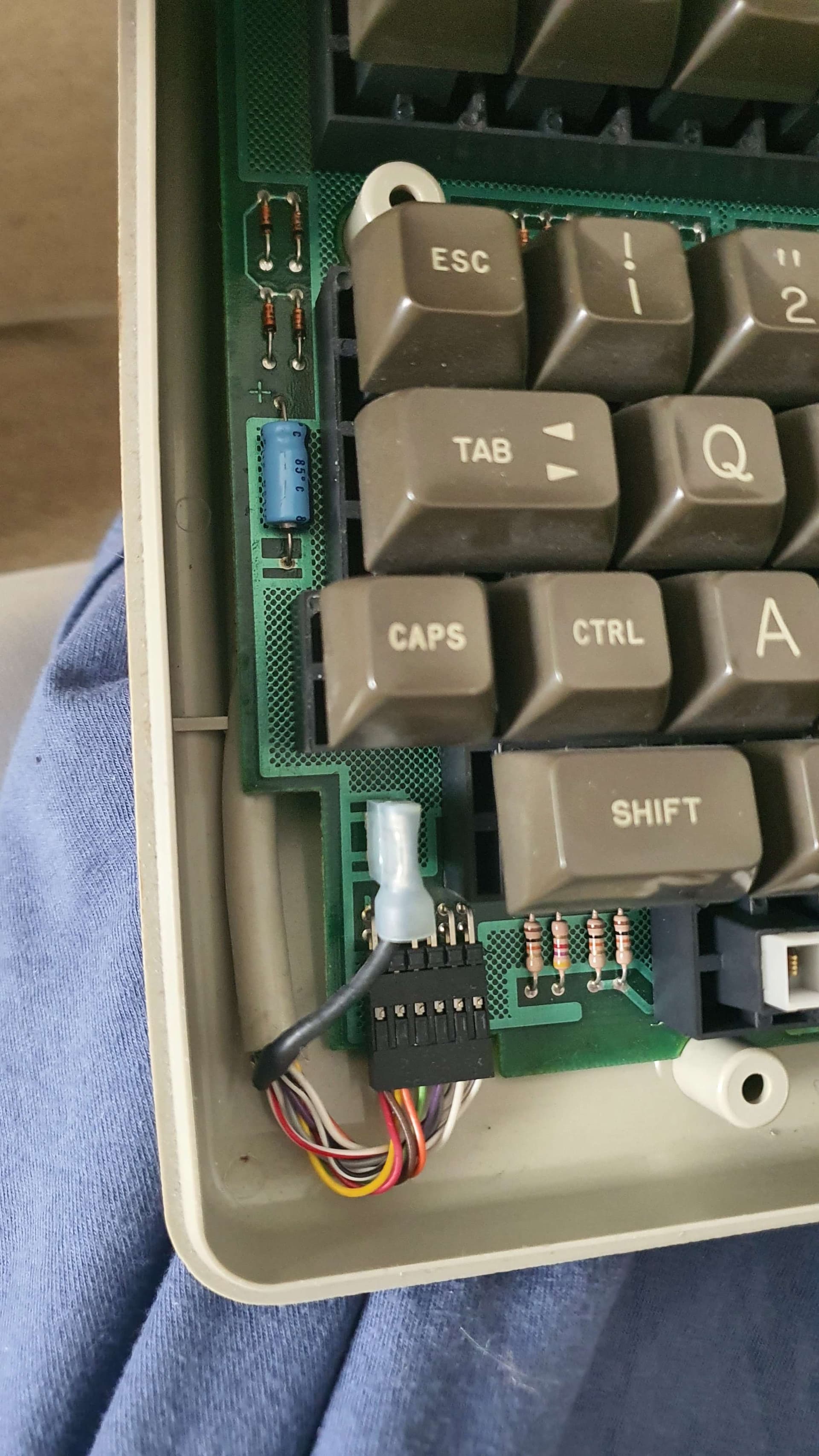
I have a very old keyboard from an HP terminal in my hands. My end goal is to be able to read the keys that are pressed with my Arduino (I'm using an Uno R3 if that matters) through the cable. The keyboard uses a DB15 connector, which I have found a diagram for online. However, I am not quite sure how to apply it. I am not new to programming but I am new to Arduino and electronics. I have tried looking up reverse engineering keyboards, but most people seem to just solder wires directly to the IC on the keyboard PCBs but I'd like to keep the original cable.
I would appreciate if anyone could point me to any resources or reading material that could help me with this problem specifically, as the stuff I found online is either very general or not applicable.
So far I have tried wiring up the inputs to the pins and using digitalRead() on them, but nothing changes when the keys are pressed.
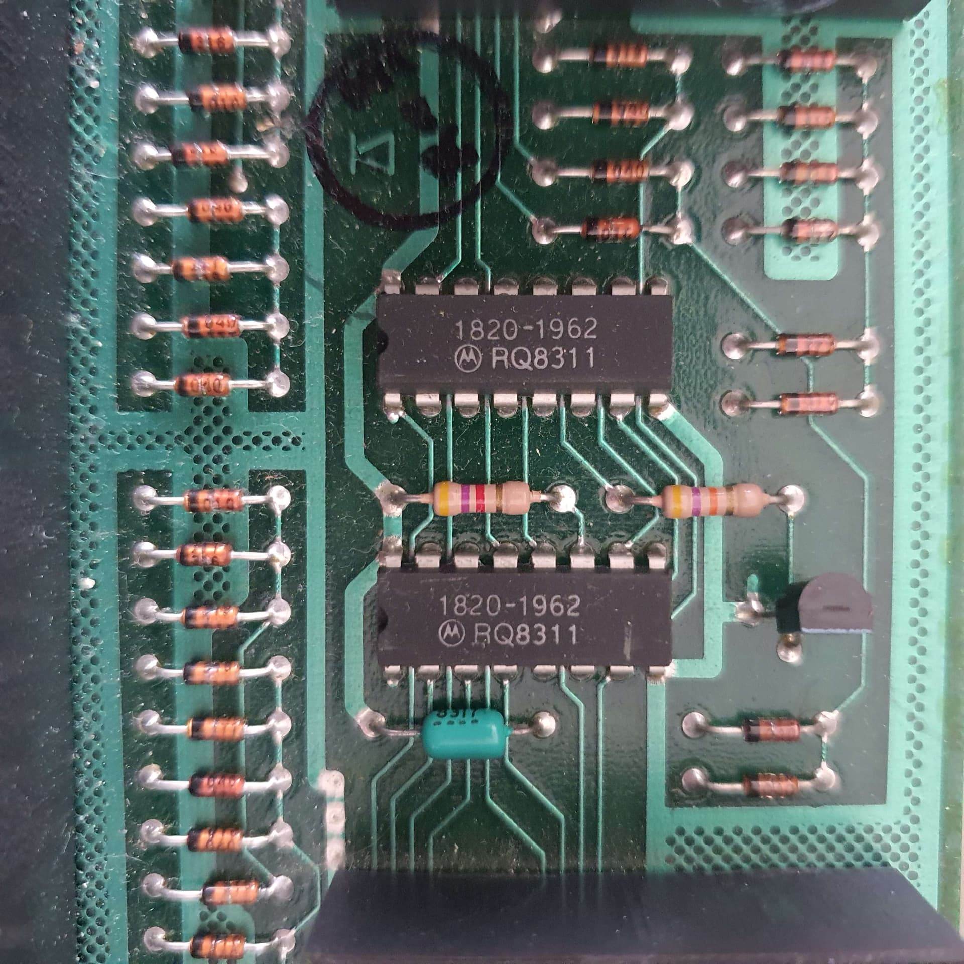
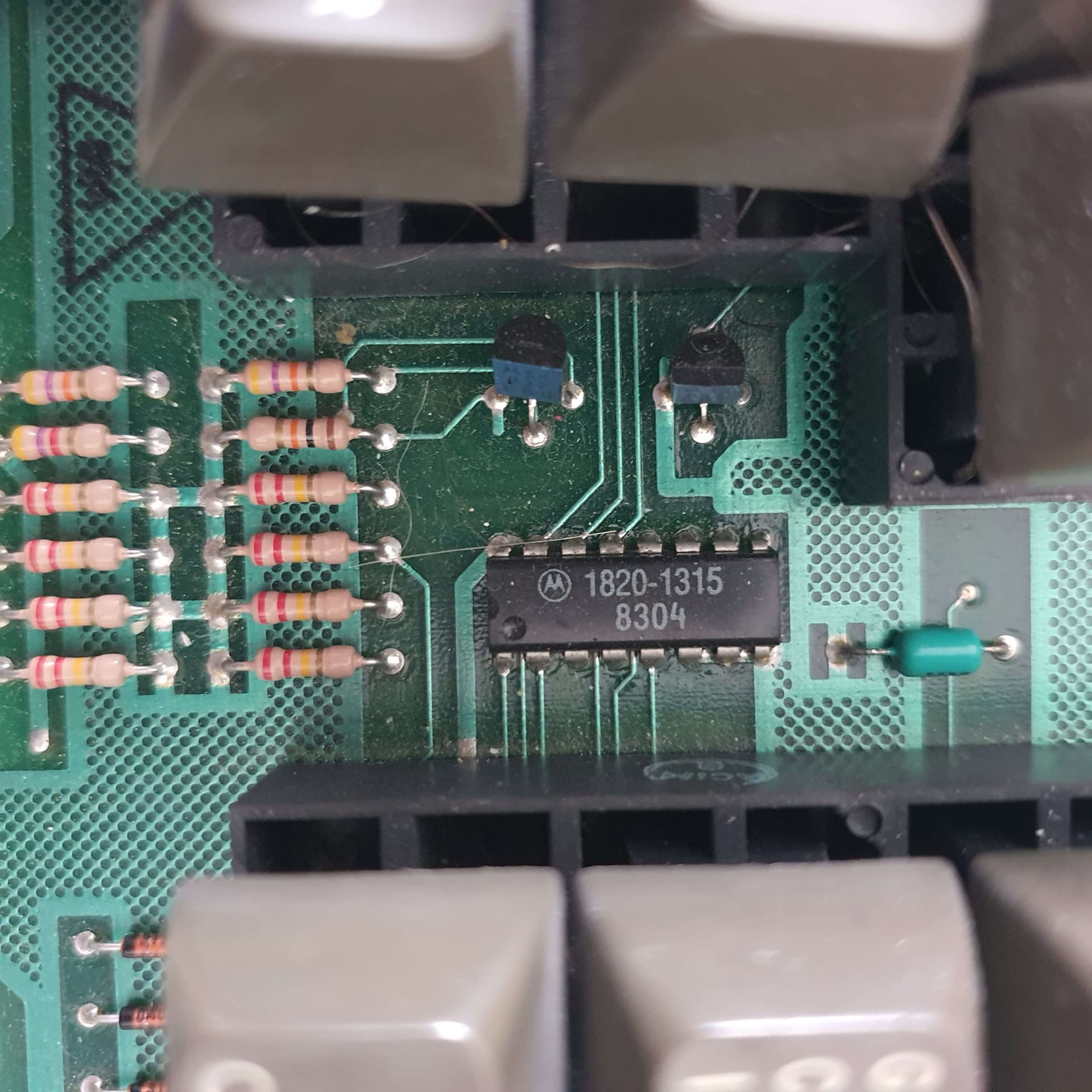
What circuitry is there inside? IC names...?
The out likely produces a serial signal. My wonder is if it's TTL or RS232 signal.
(There might exist a converter making the voltages used in RS232.)
Not that it will help you figure out how to interface but the chips use HP's proprietary numbering scheme. The 1820-1062 is a 74HC4028 BCD-Decimal decoder and the 1820-1315 is a MC14051 8-channel mux.
The RQ8311 is a date code.
Duh, now I see it's already in the fine print in post #1.
Yeah, my original plan was to try and get at least some sort of response from the connector and figure out what it means after that, but so far no luck. It helps at all, digitalRead reads pin 1 as 0 and 2, 3, A, B, C and D are all 1.
This type of keyboard was used on XT and AT PCs.
They used the RS232 logical protocol and 15V RS232 electrical protocol.
You may have to use a module with the RS232 chip.
I'll do some research and then tell you what I found.
If you can use a logic analyzer to see what is going on with those pins it would be helpful. If my guess is right, a HIGH or LOW on OUT would indicate valid data on 123:ABCD and you could record that with a digitalRead.
All speculation though without seeing what signals appear on the pins.
Remember OUT is open collector so will need to be pulled up to 5V.