I understood the basics of a voltage divider. The ratio between resistors is important. But between a 20K[ch937]/10K[ch937] voltage divider and a 2K[ch937]/1K[ch937] one, which one is the best ?
I have to deal with a 80V power supplie. I have to.
I have to use this power supplie to feed 2 things, 1 device that need this 80V, and the arduino UNO who needs between 7V and 12V according to arduino website.
So, .... I am about to use a voltage divider, to lower the 80V, until 9V.
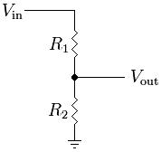
IF i use R1 = 2,53 K[ch937] and R2 = 20K[ch937], i have =
Vout = R1/(R1+R2) * Vin
Vout = 2530/(20000+2530) * 80
Vout = 8, 98 V
OK fine, but should i use R1 = 2,53 K[ch937] and R2 = 20K[ch937] or R1 = 25,3 K[ch937] and R2 = 200 K[ch937], or smaller, or bigger resistor ?
Should i use something to protect the Arduino ? from what , I don't know, maybe if the divider don't work very well or gives more that 9V in a brief time ... something like a voltage regulator ?
:-? ..... heuu i was .. i should not ?
In fact, i wanted to provide power for the Arduino AND. ...
I have to sense the 80V on a Digital Input too.
Is the voltage divider too dangerous for this ?
In addition to selecting the proper resistor ratio, you need to consider how much current will flow through each resistor, using V = IR. 80 = I * 2530 results in I = 31mA.
Now, how much power is that? P = IV. 0.0031 * 80 = 2.53 watts. So, make sure you choose a resistor that can dissipate at least 2.6 watts.
the divider is R1 = 2000[ch937] and R2 = 30 K[ch937] ??? and R1 has to dissipate 3,2W ??? what about R2 ???
If provide power to the UNO from a 80V power suplie with a voltage divider is too dangerous, i can do it with a 9V power supplie. it just would be easier to have just 1 power supplie in my box that feed both circuits.
But for sure, i need to trigger actions with the UNO, sensing 80V on the input. So it's pretty important for me to have a secure voltage divider.
So, i must forget the voltage divider to provide power for UNO.
I will search for voltage regulators as you say.
Do You think that it will do the job to sense the 80V. do you think these values are good ?
R1 = 2000[ch937] and R2 = 30 K[ch937] and R1 has to dissipate 3,2W
To get the power for your uno you cannot (well you can but it'b totally stupid unless all you had was a bunch of expensive high power resistors) use a voltage divider because of the heat dissipated in the dropper resistor and/or the voltage regulator. What you need is a switch-mode power supply that can happily accomodate your 80 volt input and will output the required 9 volts. Because of the way switch mode units operate the input power will be about 120% or less than the output power. So your 9 volts at up to 500ma equates to 4.5 watts so your switch mode PSU will only pull say 5 watts out of your 80 volt supply, with very little heat generated.
You can of course use a simple dropper system for your measuring circuit because it is delivering practically zero power. However, for accuracy of measurement, you need to take into consideration the input impedance of the uno since it will form part of the divider chain.
Start by letting a reasonable current flow down the chain. let's say 5ma. Total power dissipated = v x a = 80 x 5 /1000 = 0.4 watts
R = v / i = 80 x 1000 / 5 = 16k ohms
Divider ratio = V(r1) / V(r2) = 75 / 5 = 15 : 1
This only gives us a rough guide. What we now need to do is consider uno safety by permitting an allowance for the voltage to rise above 80. Let us use +50% so now base calculations on the voltage being 120. The resistor ratios do not change since ratio is ratio irrespective of values.
Calculations still to be based on a chain current of 5ma and because the uno has a high input impedance we shall "choose" to ignore it.
V(r2) = say 7.5 volts (This allows your 80 volt supply to rise to 120volts without damaging the uno)
V(R1) + V(R2) = 7.5 + 112.5 = 120 volts (which was where we started from)
Power dissipation in R1 = V(R1) * I = 112.5 * 5 / 1000 = 0.562 watts (Note that this figure is higher than the original 0.4 since we are now basing calculation on 120 volts)
Power dissipation in R2 = V(R2) * I = 7.5 * 5 / 1000 = 0.0375 watts
So R1 should be rated at say 1 watt and R2 rated at 0.25 watt
Ok RICHARD. Here is some explanation. Excuse my english, i try the best i can...
The Arduino circuit is made to complete a system already in place.
The system purpose is to trig fireworks, but .. in an "vintage" way.
The guy is making a contact on a piece of metal (rivets), that close a 80V circuit. 80V are necessary to travel very long cables until few igniters. The number of igniters and the long distance between the guy/ the source, and the igniters, force us to have 80V.
the 80V battery is made with a bunch of LR6 1,5V battery.
the guy works for years with this system and he won't change it. I have to deal with it.
So this "trigger box" is made with a matrix with 6 lines of 10 piece of metal (rivets), and the guy have a meter probe in his hand (the one that you can find on a multimeter) and touch a rivet when he wants this line of fireworks to be trigged.
The idea is to find a way to mix this system, and the arduino one.
The guy absolutly wants to keep his actual system, and be able to plug arduino inputs on few rivet. Like this he will be able to trig the "old-way" line by touching a specific rivet, and trig something else with ARDUINO, by touching an other rivet.
So he has a 80V + power in his hand, and make a contact on rivets to establish a trigger.
So this is a 80V + that will go to the Arduino Input.
I know this is a strange setUp, but i have to deal with it to implement some Arduino function in his "vintage" system.
The arduino will communicate with other arduino with Xbee, and trig stuffs in a "wireless mode", with much more flexibiliy.
Do you think there is a smarter way to mix the 2 systems ?
Here is a picture that shows the setup
thank you JackRae for your resistor values ...
Here is a picture that summarize the situation.. am I right ?
So if i want to mix the 2 systems, is this schema all right ?
If the 80V supply is just a bunch of 1.5V batteries in series, just tap off five or six of them, to give 7.5 or 9V.
(how do you get 80V from 1.5V batteries anyway?)
That would be the way to go, except that your 0V and the battery pack 0V should be the same (-80V to +80V is 160V, as anyone who has had a belt off a telex line knows!).
Do you mean this ? the first one or the second ?
can you explain to me the job of the diode in this setup ?
One more thing, about the power dissipation.
should i keep the P = IV formula ?
P = 80*5/1000 = 0,4 W ???
Hi
by "sense the 80V", i mean, if the guy touch the rivet and 80V go through the circuit. So, Is there 80V or not ?
After sensing that the 80V is there in the DigitalInput, the UNO will do actions, simple, or complexe, talking with other UNO in the field, Wirelessly to trig other stuff.