Hello,
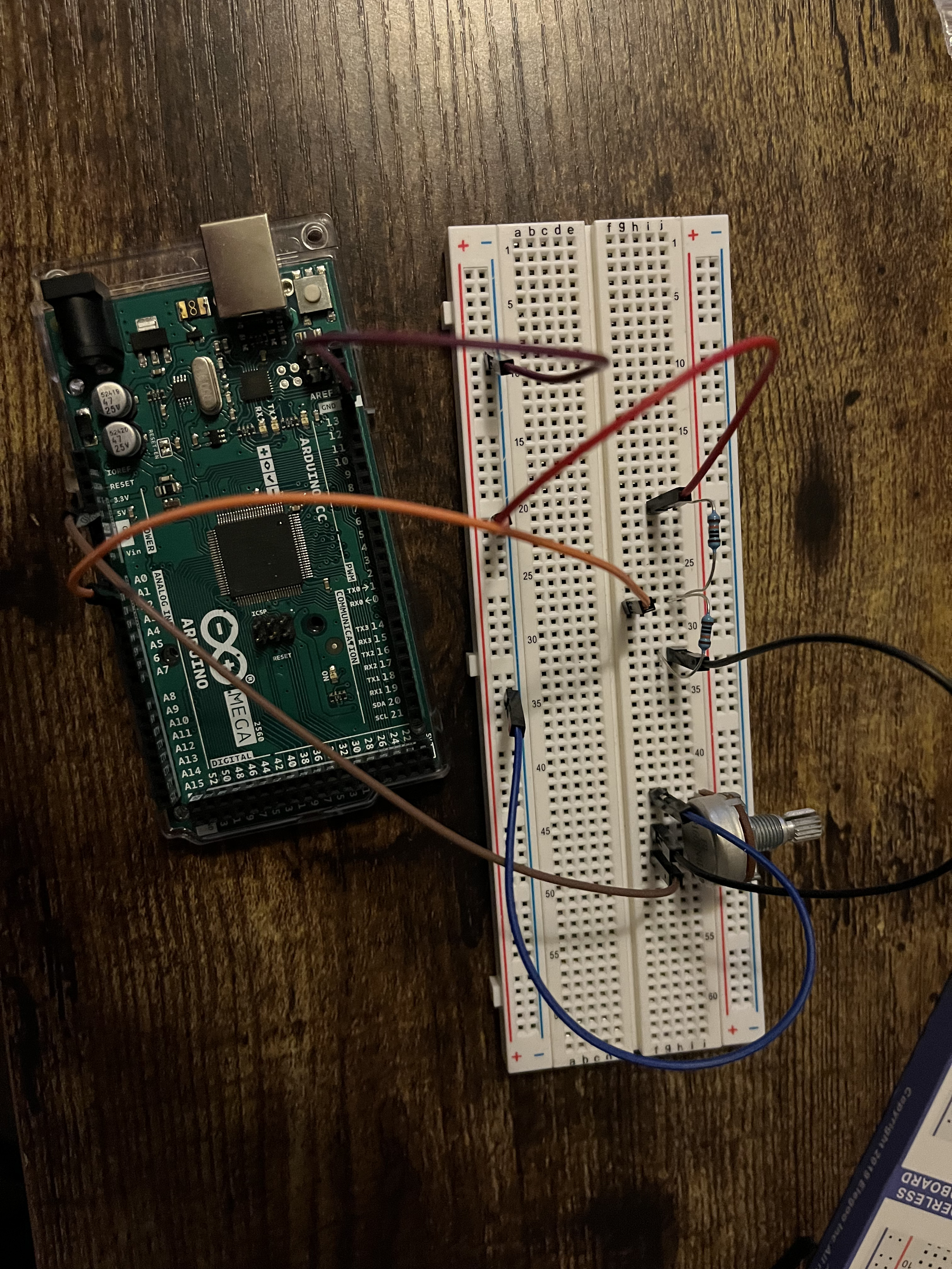
Today I was attempting to use a voltage divider to reduce the output (0-5v) voltage of a potentiometer in half. From my understanding, the equation for a voltage divider shows that using two equivalent resistors in series will accomplish this. However, when I try this with my Arduino the voltage is not half (varies depending on the equivalent resistor values). Could someone please help me with this, or let me know if im missing something (Mech-e here)? My code for reading voltage is below, as well a picture of my wiring.
The potentiometer IS a voltage divider. Why do you need another one?
Voltage dividers wired in series or parallel do not follow the "ideal" behavior of a single voltage divider. The entire circuit has to be analyzed to determine the output voltage.
See this example of a voltage divider with load resistor: Voltage Divider
When you calculate the voltage of a divide you have to include in your calculation whatever resistance is on the "output" (aka the center node of your divider). My guess is you have not.
Thank you for the response. The potentiometer was more to test if I could apply this voltage divider to a pressure transducer I would like to use with an arduino. The output of that transducer is 0-10v which from my understanding would fry the analog pin on the arduino (if the output went above 5 volts). Im guessing the same would apply for the transducer then?
Your explanation doesn't make sense....your original post has (as already explained) not a basic voltage divider.
Best you explain what you are really trying to do and then go from there.
Sorry about that, before this post I was not aware that the potentiometer also acted as a voltage divider, thus I thought using it would help me in understanding how to make the basic voltage divider.
What I am trying to do is apply a similar basic voltage divider to cut the output signal of a pressure transducer (0-10v) in half to read on the analog pin of an arduino. When I have attempted to do this, the output is not half and usually varies with the resistors that I use.
As explained, two voltage dividers connected together are not simple dividers, and require a complete circuit analysis. Did you look at the linked tutorial?
To reduce the maximum output voltage of the potentiometer to 5V, connect a series resistor between the 10V supply and one side of potentiometer, equal to the total potentiometer resistance.
Tell us the total resistance of the potentiometer.
A much better idea is to connect the potentiometer to the Arduino 5V pin, and use it as is.
I apologize I realize I have done a terrible job of explaining. The potentiometer was just supposed to be a stand in for the transducer. Just some voltage source to to test if I could create the voltage divider (I realize now it is not the same).
What I am really trying to do is cut the output voltage (0-10v) of a pressure transducer in half with a basic voltage divider (forget the potentiometer). I recently tested this with the transducer and the values were not half, but varied with the resistor values.
Divide your input voltage with the voltage divider, then before connecting it to your microcontroller use a multimeter and verify that it is within range.
If your maximum voltage from the pressure transducer is 10v, i would recommend more than halfing the input voltage to the microcontroller.
On a lot of micrcontrollers the top range of the input voltage (near 5v) is generally not as accurate with analogread, and you also gain some safety room. I suggest aim for your maximum voltage to he about 4.5v (depending what resistors you have available) then do the maths to calculate your readings.
You need to be specific on the transducer. Photo of spec sheet is general info.
Apparently most are 4-20ma output 2 wire.....doesn't really say what the 3 wire outputs are.
Link takes one to where one can select any number of models so no help there either.
Expensive bit of gear for a beginner to boot.
It would be good if you actually told us your exact model number. However, I shall assume from your data sheet that you have a TD1XXX-DD-...
Which is the 0-10V output model. IF not, tell us exactly what you have.
That output will need a resistive divider, as you have sussed already. You haven't told us your exact resistive divider values, only that they're equal. I wouldn't place any more load on the device than about 1 mA, which translates to a divider of about 10 kohms total resistance. Equally divided would be 5k top and bottom, I'd use 5.1 k upper and 4.7 k lower. Wire the junction of the two resistors to A0.
Fix your code. A0 is not an output. You do not need to set pinMode() at all for analog inputs.
Your conversion is wrong; use 1024, not 1023. Others may argue, but go to the Microchip datasheet.
Get your present 5V setup working first.
Then, it would be wise to measure your actual 5 V power pin, and use that voltage instead of "5", but be aware, this is a power value. It will vary depending on whether you're powering the board with USB, or Vin, or directly applying 5V; if you want accuracy, you'd be better to use the internal reference (1.x volts); if you do that, remember to change your voltage divider as necessary.
I used a 1Hz, 10V pk-pk sinewave, (Yellow oscilloscope trace).
The potential divider was made from 2 x 10kΩ resistors.
The junction of the two resistors went to the analogue input and also the blue oscilloscope trace.
There is hardly any signal seen on the blue trace of the oscilloscope, and the ADC count didn't get any higher than 3.
The potential divider now works correctly. 5V peak to peak signal on the blue trace, and ADC count >1000.
So it looks like that it is the:
pinMode(P,OUTPUT);
that is the cause of your problem.
Just remove that line and every thing should work correctly. There is no need to declare the pin as an INPUT, it automatically defaults to input if you don't specify anything.