I'm working on an Arduino project using a voltage divider to read a photodiode. Currently, I'm using a 2kΩ resistor, but I'm not getting full dynamic range—a lack sensitivity to lower light levels. I want to expand the voltage response to detect dimmer conditions more effectively. Should I increase or decrease the resistor value to achieve better sensitivity to low-light inputs? I'd love to hear recommendations. Any insights would be appreciated.
To get the range, we need to use very bright lights. The kit I've already built it. So a bit of a pain to open up the box. So need a game plan.
Update: This video explains the circuit. Looks like 1k resistor would be best. Also the addition of a smoothing capacitor to handle the flickering AC lights.
P.S. I don't know why the distracted post about the RGB LED was considered the solution. The RGB LED has nothing to do with the question about photodiodes.
I have used the digital light sensor recommended by Leo, to make a system for detecting how photo florescence (glow in the dark stuff) decays with time. It is very sensitive.
However:-
Can you show the wiring of this please as there are several ways you can wire this up. Also what sort of photo diode are you using? Normally these sort of things are IR sensitive and not sensitive to normal visible light. What sort of light are you using?
You might be better off using a light dependent resistor (LDR) instead.
That doesn't make any sense. The voltages produced by photodiodes are pretty small. They need boosting up, not reducing down.
Can you post a link to the data sheet for the photodiode? Also your schematic showing how it is wired to the Arduino, and a link to this "kit" you mentioned and how that is involved.
Photodiode Specification: Receive Wave Range : 400-1100 nm Response Peak Wavelength:940 nm Receiving Angle : 40° Material:Si, Plastic, Metal Head Color : Clear Head Size : 3 x 4mm / 0.12 x 0.16 inch (D*H) Pin Dia : 0.4 mm / 0.016 inch Total Length: 33mm / 1.3 inch
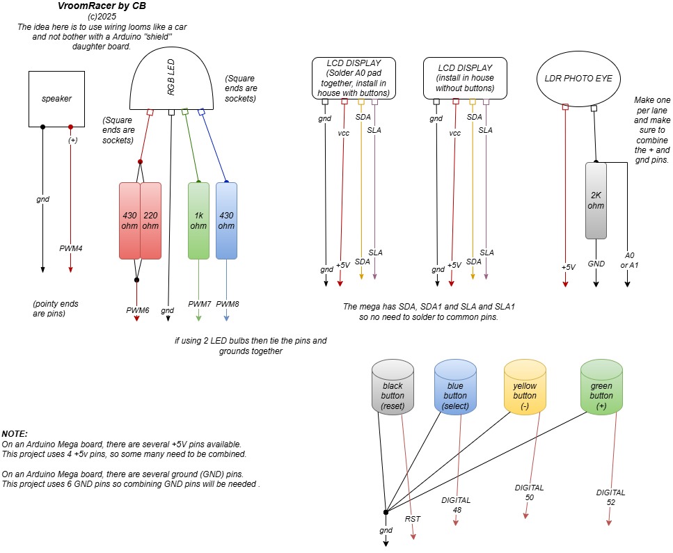
In the above chart, photodiodes can replace the LDR's but keep in mind that polarity matters. Photodiodes must be installed with reverse bias. As for the RGB LED, there are 4 leads: a ground, red, green, and blue. Please see the next image for complete details. The 2k resistors can be higher ohms for increased photosensitivity.
Using a photodiode in reverse bias within a voltage divider setup on an Arduino is a great way to measure light intensity with improved sensitivity and faster response times. Here’s how it works:
Understanding Reverse Bias Photodiodes
In reverse bias mode, the cathode (negative) is connected to a higher voltage, and the anode (positive) to a lower voltage (typically ground).
The diode does not conduct like a regular diode unless light strikes it, generating a small photocurrent proportional to the light intensity.
This configuration reduces capacitance, making the response faster.
Setting Up the Voltage Divider
A voltage divider transforms the photocurrent into a voltage signal that the Arduino can read. Here's a basic setup:
Connect the Photodiode in Reverse Bias:
Cathode → VCC (e.g., 5V or 3.3V)
Anode → One end of the resistor
The other end of the resistor → Ground
The junction between the photodiode and resistor becomes the output voltage.
Selecting the Resistor Value:
Use a pull-down resistor (e.g., 10kΩ to 1MΩ).
Higher resistance increases sensitivity to low-light conditions but may slow response time.
Lower resistance improves response speed but may reduce sensitivity.
Reading the Voltage with Arduino:
Connect the voltage junction (between the photodiode and resistor) to an analog pin (A0, A1, etc.).
Use analogRead(pin) to measure the voltage, which varies based on light intensity.
Arduino Code Example
const int sensorPin = A0; // Photodiode voltage divider junction
void setup() {
    Serial.begin(9600);
}
void loop() {
    int sensorValue = analogRead(sensorPin); // Read voltage level
    float voltage = sensorValue * (5.0 / 1023.0); // Convert ADC value to volts
    Serial.println(voltage); // Print voltage to monitor
    delay(500);
}
This setup allows you to track changes in light levels and adjust the resistor value for better sensitivity.
Asking copilot, it suggests 10k. Perhaps I could use little pots (like the little screw driver kind) to tune the resistance.
On my project, I wired it wiring loom style (like a automobile) rather than a daughter board "shield", so it's easier to swap out. I was just wondering what humans had to say.
Humans can tell you the truth and point out your inconsistencies.
First of all in your diagram you call it a light dependant resistor. Then you call it a photo diode. these are two different things
So what do you actually have?
The diagram also shows all the wires to the RGB going into one connector. That is not how it is wired.
Schematics are important things to get right, otherwise they just no help at all.
I have made 3 devices, the first two used LDR's, the last one I am trying photodiodes.
As for the RGB LED diode, there are 4 leads, a ground and a red, green, and blue. I thought that was common knowledge and hence didn't bother to go into greater detail. In the documentation, I have added a note for future readers. Also the RGB LED is outside the scope of this inquiry.
This type of amplifier is much beloved by people who make voltage controlled oscillators when reproducing the original Moog modular sound synthesisers. Unfortunately they are getting increasingly rare / expensive as a quick look at eBay will show you.
Also you will need to add a range of resistors into your collection of 1MΩ to 10MΩ to design things. Values you would not normally use with most Arduino circuits.
WokeNote:-
Transimpedance amplifiers are not amplifiers that self identify as voltage driven amplifiers.
Absolutely nothing is outside the scope of asking for help here. We show you and tell you what is wrong. If we just concentrated on the specifics of an inquire we would never be able to solve half the problems we do. The point is that you don't know, so you don't know what to ask.