You would have to show how you did that. Theres something wrong.
I am using +-5% resistors
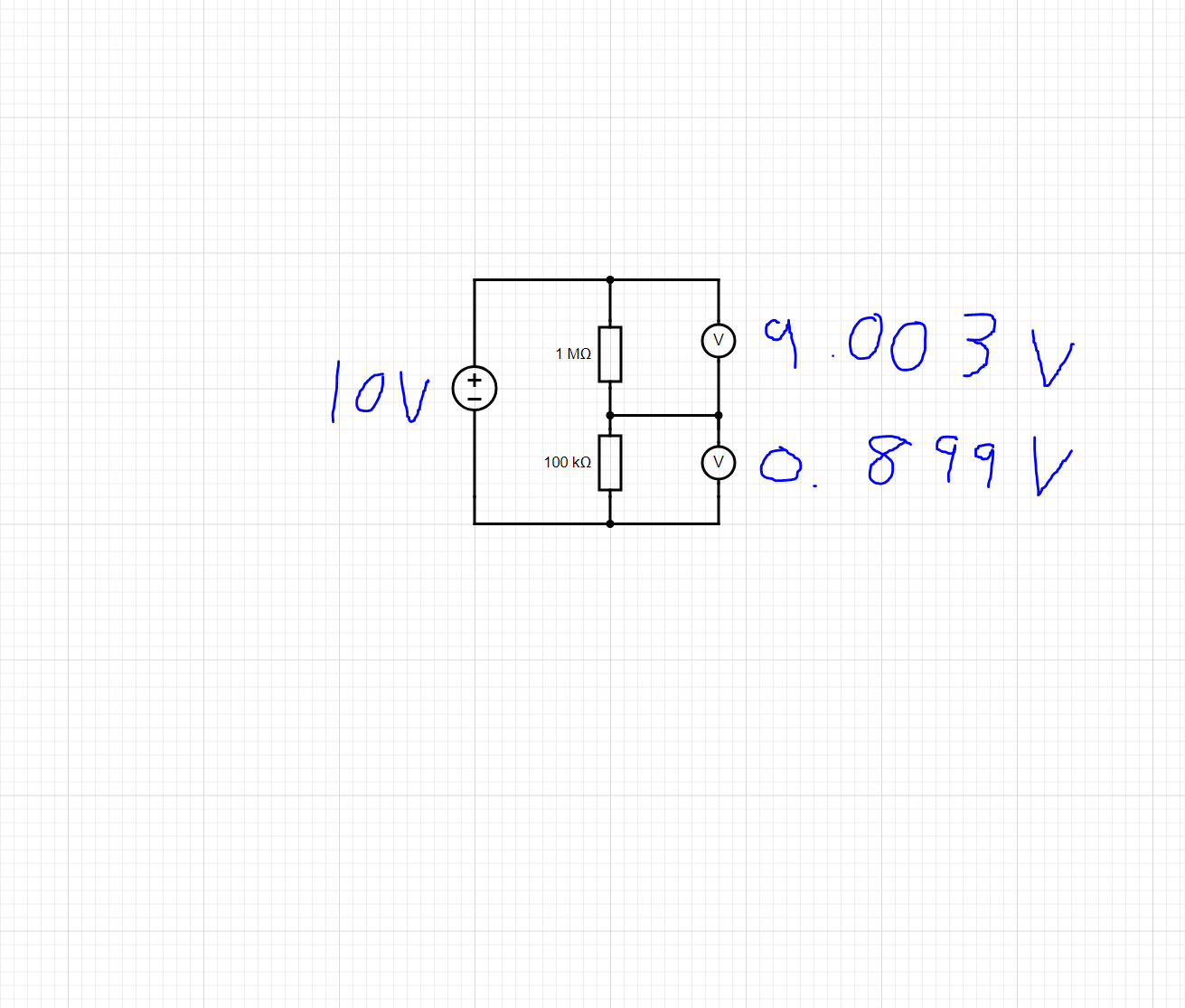
I apply 10V and measure the voltage across each resistor. i took these measurements one after each other using a multimeter but just added both on the same circuit
Then i did 9.003/.899=10.0144605 to get the ratio
You`ll need something like this for a probe: You can see voltages and dissipation figures on the schematic, cheers.

The only critical part is a R1, as it should dissipate 2.25W (if 100M value is used).
1 Like
Are you aware that 9.003 + 0.899 does not equal 10.000?
Come on man, you are distracting the guy who is beginner with trivial things, can you measure those two voltages with DMM and get the correct sum at 3 decimals ??
Anyway, your test, voltage divider is ok, now get the software working.. Btw, you`ll get 0 ADC if you connect input of the divider to gnd.
i did think that im not sure what is going on i measure from top of R1(1M) to the bottom of R2(100K) i get 9.988V but then across each resistor i get roughly 9v/0.9V so im not sure where the other 100mv is getting dropped
Thank you, im guessing that D3 would need to be a Zenner diode to protect against voltages over 5V but what would i need for d4?
Most multimeters have a 10MΩ input resistance, when you connect this across the 1MΩ then you end up with the parallel combination of 1M and 10MΩ.
Your 1MΩ is now effectively 909091Ω.
This upsets the division ratio of the potential divider.
The effect is less noticable when measuring the voltage across the 100kΩ, but is still present.
Calculate the division ratio from the resistor values.
i tried this and got 993k(1M) 99.2K(100K) i put these into the code with a ratio of 10.01
i am still getting out readings but it seems to go up by .41V for every 5 volts i increase im guessing this is something to do with part of how the Arduino works but im not sure

That is all right, those are trivial things..
Yes, D4 should be zener, and D3 could be any general purpose diode.
1 Like
@mj_0305
There is no way I would connect 15000V through some resistors to my Arduino without some type of galvanic isolation.
If any component should fail, there goes your Arduino and the computer it was connected to and maybe you.
D3 and D4 are useless
People who monitor only 220V use isolation devices for safety reasons.
1 Like
Whilst it may seem a good idea to have a zener diode across the lower resistor in the potential divider, it may be more trouble than it is worth.
A zener diode will start to conduct in the reverse direction at a lower voltage than it's rated zener voltage.
This will cause a non-linearity in the response of the potential divider.
At the moment your potential divider's response is nice and linear:

You could multiply all your readings by a 'calibration factor' of around 1.0866 to get the correct value.
The error that you are getting may now be due to the fact that you are using a value of 5.0V as the reference voltage when in fact it is likely to be less. try measuring the reference voltage/Vcc and use that figure instead of 5.0.
1 Like
Somebody said it`s going to be connected to the computer?
You are right, I forgot about large resistance..
Is there another reasonable way to program your arduino and test the running code?
I was planning on having the whole circuit enclosed in an insulated box running off a 12V power supply with just a hole for the LCD to be mounted
Yes, look at the code , there is a display, I hope that nobody in the right mind would test it without galvanic isolation.
Anyway, OP should clear things, where this device, will be used?
Still dangerous.
OK if you use a battery. Then if anything fails, all you loose is the arduino
1 Like
Thank you i changed the 5 to 5.45 in the line below and now it is reading within .1 of what i am applying to it
float Vcalc = (5.45/1024)*VoltageMsmt;
Im also just curious how you worked out what the calibration factor should be
i will try this instead im guessing a 9V PP3 battery will be best and just use a switch to turn this on/off