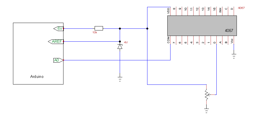
It's not unusual to see a small delta in a voltage regulator's output voltage related to current draw (although part of what you are seeing might be due to path-loss, too, depending upon where you are measuring).
If it's too much for you, you might consider using a separate regulator to power the LEDs.
Also -- if the Arduino is sinking the LED current, there might also be a small delta in voltage at internal ADC's ground reference due to a shift in the Arduino's reference "ground" voltage.
This latter is probably very small, but I'll give you an example of where it was a problem for me.
I was working on a PIC design that was part of a frequency-lock feedback loop. That is, the PIC was measuring the frequency delta between a voltage-controlled oscillator and a reference frequency, generating a PWM signal that, after being heavily filtered in the analog domain, drove the voltage-control input of the oscillator.
While debugging, I noticed that the oscillator's frequency would consistently drift in one direction, then reverse and move in the opposite direction. It would repeat this pattern at about a 1 Hz rate.
Coincidentally, one of the PIC's outputs was tied to the cathode of a small "heartbeat" LED that blinked at a 1 Hz rate (the LED's anode was tied to 3.3V through a resistor), so the PIC output was sinking a small amount of current (5 mA?) every 500 msec.
The drift exactly corresponded with this LED's heartbeat.
I removed the LED and the drift stopped.
My hypothesis was that the small delta in ground current introduced into the PIC's internal ground, ground lead, and finally the connection to the board's ground plane when the PIC was sinking LED current created a voltage delta that changed the PWM voltage (which was also referenced to that same PIC ground), as seen by the VCO, just enough to shift the VCO's frequency.
Anyway -- the point of the story is: if you want to make very accurate ADC measurements, be aware of all possible sources that might corrupt your readings.
