Voltage regulator help

Hi,

Can anyone see the issue with my circuit voltage regulation? Any help would be amazing, thanks in advance.

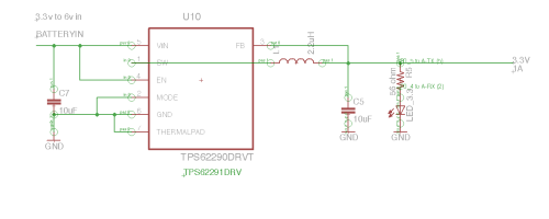
I chose to use this step down regulator, TPS62291DRVT. I have a circuit running at 3.3v by battery and it is pulling around 600mAh.
Data sheet: http://www.ti.com/lit/ds/symlink/tps62290.pdf

I found this circuit on the data sheet which isn't working on my PCB at all and am not sure where I have gone wrong: http://25.media.tumblr.com/dea207a1bebe3b7540e357b27afe41e3/tumblr_mt2ajmtC7i1so48cuo1_500.png.

Here is my circuit and PCB:

PCB image: http://31.media.tumblr.com/e061d5e1ebe186f75b36704477860d04/tumblr_mt2am1vNTh1so48cuo1_500.png

This was the inductor I used: http://uk.farnell.com/wurth-elektronik/74479775222/inductor-pmi-0805-2-2uh-0-7a-20/dp/1869750?Ntt=1869750

At the moment, when I power the circuit with 6V the output I get is 0.75mAh.

recheck your wiring, pins... or buy a cheapy prebuilt for a couple of bucks

In the circuit diagram there is a component labeled L1.

I interpreted that as an inductor and used this http://uk.farnell.com/wurth-elektronik/74479775222/inductor-pmi-0805-2-2uh-0-7a-20/dp/1869750?Ntt=1869750.

Was that correct??

The inductor is to clean up the waveform / buffer it.

your problem is before that even takes place.

No, cjdelphi, that inductor is not "to clean up the waveform / buffer it."

That is a switching regulator IC. The inductor acts as an energy storage device, -not- a filter.

That inductor is rather small for a switching power supply. There is a good chance that it is saturating.

I'm unsure what the OP is saying. Are you saying that the circuit is drawing 600mA with no load attached? Or that it is drawing 600mA from the power source, while only outputing 0.75mA (not mAh) to the LED? What is the color of LED? What forward voltage is it rated at?

Use the TPS62290. See the first circuit in the datasheet? Replace R1 with the LED, and use a value of R2 that will pass the required LED current with 0.6V dropped across it. In that way, you are regulating the current rather than regulating the voltage while hoping that the voltage drop due to increasing temperature doesn't cause current to increase too much.

And use an L1 rated at least 2A.

Are you using the specified 10uF 6.3V chip ceramic capacitors? Or did you just wang in some aluminum electrolytics?

Edit: That last bit wasn't meant to sound as snarky as it appears.

polymorph:
No, cjdelphi, that inductor is not "to clean up the waveform / buffer it."

That is a switching regulator IC. The inductor acts as an energy storage device, -not- a filter.

You're wrong, it's to help filter the output. (You even said "energy storage") as the magnetic field builds up it will allow dc but not ac to pass thus filtering, cleaning the signal.

cjdelphi:
You're wrong, it's to help filter the output. (You even said "energy storage") as the magnetic field builds up it will allow dc but not ac to pass thus filtering, cleaning the signal.

Sorry cjdelphi, but you're wrong. The purpose of the inductor is energy storage.

If it truly was there to "just filter" the supply would function without it. That's not the case. Without the inductor the switching supply wouldn't work.

Your "it filters because it blocks ac" argument could be extended to a ridiculous statement like: the inductor a current limiter... because it as resistance associated with it. Again, that's not the purpose.

Buck converters are strange things to many people.
Heres a good simple explanation of how they work.
http://www.ecircuitcenter.com/Circuits/smps_buck/smps_buck.htm

And yes, the Inductor is a critical part of the converter.
So is the catch diode which you cant see because its inside the IC

How's the inductor prevent the ic from working if say replaced with a wire? So how is the inductor related to the sense pin?

cjdelphi:
How's the inductor prevent the ic from working if say replaced with a wire? So how is the inductor related to the sense pin?

look at this Switching Regulator
and at mauried's link :slight_smile:

Ok after a bit more reading..

I think i got it, due to the high frequency switching the caps alone can't prevent the ripple so the inductor is used to prevent the ripple which causes the ic to stop functioning...

The inductor then cleans the signal as i originally stated then, as the energy is built up in the inductor when the ic switches off the inductor lets it magnetic field release...

I'd like to get an oscope out on one of these circuits, it should output a voltage (how else does the inductor produce / collapse the magnetic field to begin with?!)

Wow, you should really let Texas Instruments know about this so they can correct the datasheet!

Page 15:

OUTPUT FILTER DESIGN (INDUCTOR AND OUTPUT CAPACITOR)
The TPS6229x is designed to operate with inductors in the range of 1.5?H to 4.7?H and with output capacitors in the range of 4.7?F to 22?F. The part is optimized for operation with a 2.2?H inductor and 10?F output capacitor. Larger or smaller inductor values can be used to optimize the performance of the device for specific operation conditions. For stable operation, the L and C values of the output filter may not fall below 1?H effective inductance and 3.5?F effective capacitance.
Inductor Selection
The inductor value has a direct effect on the ripple current. The selected inductor has to be rated for its dc resistance and saturation current. The inductor ripple current (?IL) decreases with higher inductance and increases with higher VI or VO.
The inductor selection has also impact on the output voltage ripple in PFM mode. Higher inductor values will lead to lower output voltage ripple and higher PFM frequency, lower inductor values will lead to a higher output voltage ripple but lower PFM frequency.

cjdelphi:
The inductor then cleans the signal as i originally stated then, as the energy is built up in the inductor when the ic switches off the inductor lets it magnetic field release...

No, you are close, but still missing the point. The inductor's purpose is not there to "clean up" the signal. In fact, the inductor creates quite a bit of voltage ripple in the circuit, which is why there is a capacitor in the circuit.

The inductor is the primary energy storage device of the circuit. When the transistor turns on, it charges up the inductor's magnetic field so that it can provide the current when the transistor is off. That isn't "filtering". That's energy storage. The entire purpose of the circuit is to minimize the losses of the transistor. So if there isn't an inductor there, the switching regulator won't function.

After the switching circuit you may see a filter composed of an inductor and capacitor. In which case THAT inductor's purpose is to filter, or as you say, "clean up", the signal.

cjdelphi:
it should output a voltage (how else does the inductor produce / collapse the magnetic field to begin with?!)

The IC outputs a pulse-width modulated signal. That's the whole point. Unlike a linear regulator where current is constantly flowing through the transistors, a switching regulator switches. When the switch is off, ideally no current flows so no losses. When the switch is on, ideally it is a short so no losses. A boost configuration allows for a higher output voltage while a buck configuration allows for a lower output voltage, relative to the input.

1ChicagoDave:
Wow, you should really let Texas Instruments know about this so they can correct the datasheet!

Yes, I'm being pedantic around the use of the word "filter." One of the functions of the inductor is to form a filter. However, the primary purpose is not to act as a filter as cjdelphi describes. It's a fine line, but I'm trying to stress how the parts are actually working, and not focused on what people call them.
When it comes to electronics, everyone should be pedantic.

I strongly recommend the above links, plus "Switching Regulators for Poets: A Gentle Guide for the Trepidatious" by Jim Williams.

http://cds.linear.com/docs/en/application-note/an25fa.pdf

IMPORTANT QUESTION.... Apart from all the twaddle about L1 and how it works. :expressionless:
dt08bdk has your problem been solved?
I'm not sure about your choice of L1, it is rated at .7A, it should be okay for your application. The current rating also dictates the DC resistance of the inductor, but I don't think in this case it has any effect on getting the chip started or regulating.
Tom 8)
Also your PCB image tells me nothing as you have not included an overlay to identify even the IC and inductor.
For example pin2 and pin 6 should joined together with the thermal pad, where is this on your pcb image?

polymorph:
When it comes to electronics, everyone should be pedantic.

And not say things like this:

I have a circuit ... pulling around 600mAh.

He presumably means mA...

JimboZA:

polymorph:
When it comes to electronics, everyone should be pedantic.

And not say things like this:

I have a circuit ... pulling around 600mAh.

He presumably means mA...

Depends, he could have set there for an hour :slight_smile:

cjdelphi:

JimboZA:
And not say things like this:

I have a circuit ... pulling around 600mAh.

He presumably means mA...

Depends, he could have set there for an hour :slight_smile:

You even see something like "600 mAh per day" or "880 kWh per year",
which is more intuitive for most people in certain circumstances than their equivalent 25mA or 100W

(For most people, its not intuitive at all, to get the dimensions for totals and rates right)