I am very confused as to what i need for my project. Ive been told that i require a MC78L08ACP Voltage Regulator but cant seem to find any nearby what is a good alternative i can use.

I am very confused as to what i need for my project. Ive been told that i require a MC78L08ACP Voltage Regulator but cant seem to find any nearby what is a good alternative i can use.
78 Series voltage regulators are a family with similar but not quite exactly the same characteristics. You may be able to substitute a more readily available variant, but you have not described your project or specific requirements.
Because it looks like you are only trying to power the Nano through Vin, as long as your more available substitute(s) can deliver a minimum of 7 VDC and no more than 12VDC (better to be closer to 7) you should be OK. Follow the datasheet for what you select to determine if you need different capacitors.
Also "Vcc" is not the same as Vin. Vcc refers to powering the chip and for a Nano that is (corrected) 3.3V. Nano does not have a Vcc pin. That may seem like semantics but it makes me question your design source at least a little.
I would actuallyy suggest you just use a 7805, and power the Nano through 5v. easy enough and you should then change C2 into a 1uF Cap.
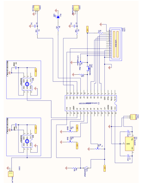
On closer look it appears you are already powering the 5V pin but the image resolution is not good enough for me to tell what you are doing.
im sorry for my lack of knowledge i appreciate your suggestion. Would it be possible for you to explain to me why the C2 needs to be reduced and also why C1 is left unchanged
The problem finding that specific part number is it's obsolete. That can be seen here in the On-Semiconductor Data Sheet. Actually you are referencing a 8.0 volt regulator and not a 5.0 volt regulator. Guessing you want a 5.0 volt regulator? The 08 in the part number implies 8.0 volt regulator. Iff you want the 5.0 volt version this is what you want for new designs. Max current 100mA in a TO 92 case. Slightly lower dropout voltage than its predecessor with 1.7 volts. The data sheet will reflect the 0.33 uF on input and 0.1 uF on the output.
The MC78L00A Series of positive voltage regulators are inexpensive, easy−to−use devices suitable for a multitude of applications that require a regulated supply of up to 100 mA. Like their higher powered MC7800 and MC78M00 Series cousins, these regulators feature internal current limiting and thermal shutdown making them remarkably rugged. No external components are required with the MC78L00 devices in many applications. These devices offer a substantial performance advantage over the traditional zener diode−resistor combination, as output impedance and quiescent current are substantially reduced.
Ron
Well i tend to look at the datasheet and it's suggested typical application. they say 0.33uF on the input and 0.1uF on the output, and those are the minimum requirements for ripple rejection. I tend to use 10uF on the input and 1uF on the output, main thing to keep in mind is that if the capacitor on the output is really to big like 100uF, the 7805 will break. Many times i have another regulator somewhere dropping down to 3.3v, and then i find it good practice to step down with capacitors in 10x steps. Explain is a big word, and 10uF on the output is also OK.
What is a little unclear to me is what type of Arduino you are using ?
im using an arduino Nano
i am honestly not sure which one i need, whether it is the 8V or 5V one, the one listed to me is an 8V volatage regulator. This main IC is an Arduino nano. As you have mentioned yes it is obsolete im asking for assistance for one that can be used in place of this one
I mentioned a few links as to the obsolete version and the new version. Your schematic is hard to read. The actual chip for the Arduino Nano is a 3.3 volt chip and your drawing reflects a chip not the Arduino Nano complete board.
"The nano Iot uses a Arm® Cortex®-M0 32-bit SAMD21 processor, this is a 3V3 only processor, never connect anything that produces a voltage greater than 3V3 to that device. This normally means using 3V3 to power your sensors. To allow you to power it from a regulated 5V supply, using the onboard regulator.Feb 11, 2022"
The board can operate on an external supply of 6 to 20 volts . If supplied with less than 7V, however, the 5V pin may supply less than five volts and the board may be unstable. If using more than 12V, the voltage regulator may overheat and damage the board.
So are you powering just the chip or an Arduino Nano board? Your drawing reflects a chip not a board. The Nano board has an onboard regulator and the board can be powered by 5.0 volts.
You choose your regulator for your application. The regulator part numbers run in a series. Part of the part number is the voltage out for the regulator. So for your drawing do you want 8.0 volts, 5.0 volts or ?
This data sheet gives all the possibles for the replacements of what you initially wanted. You want the 8.0 volt flavor as that is what your initial post stated then you want a MC78L08AC, AB .
Ron
Well alrighty then looks like an 8 volt regulator so the new replacement would be a MC78L08AC, AB the AC, AB suffix is up to you and covered in the data sheet I linked to.
Looking at the drawing and your choice but for the LCD Display 2X16 in the interest of making things simpler you may want to consider a LCD with the I2C feature. I have been using a few SunFounder LCD displays with the I2C board included. This gets your LCD interface down to 4 wires. Give this a read. On the NANO it would use A4 (SDA) and A5 (SCL) so you would have to move your analog in on A4 to A6. Anyway just something to consider.
Ron
Google;
LM7808 TO92
or
78L08
Tom.. 


Thanks for the suggestion, from the reserach ive done the Arduino nano board can take a max input voltage of 5volts right? so why does the schematic diagram use an 8 volt regulator will that not be too much for the board or am i missing something.
Go HERE and click on Datasheet. Look under Power on page 2. You are providing an input voltage into Vin (Pin 30). The datasheet states between 6-20V can be applied to pin 30.
Part of the confusion comes from the nano symbol on your schematic indicates it's an IC chip and pin 30 is labeled as Vcc, not Vin. There is a difference.
Study this datasheet cover to cover