Hi everyone How are you.I am working on a Project right now in which I am using Esp32 with UWB to get distance. Now We can also send reading received by MQTT but I need to get the readings by Ethernet via W5500 Module. No when write code only for uwb i can get the distance readings from another similar PCB.But when I add code for W5500 both devices are initialized but UWB is not getting reading from Tag and When i add delay to initializw W5500 the I can recieve distance readings but W5500 failed to initliazed.Please Note W5500 and UWB are on Seprate SPI busses W5500 is on HSPI with different Cs and UWB is on VSPI.Can any body has any idea why this is happening.As i am using seprate SPI busses why its not working properly I can share more If any one has idea about this Thanks
I amusing Ethernet lib for W5500.Also below you can take a look at my code
#include <SPI.h>
#include <Ethernet.h>
#include "DW1000Ranging.h"

// SPI pins for W5500
#define HSPI_SCK 14
#define HSPI_MISO 12
#define HSPI_MOSI 13

// Chip Select pin for W5500
#define W5500_CS 15

// SPI pins for UWB
#define SPI_SCK 18
#define SPI_MISO 19
#define SPI_MOSI 23
#define DW_CS 5

// Control Pins for UWB
const uint8_t PIN_RST = 27; // reset pin
const uint8_t PIN_IRQ = 34; // irq pin
const uint8_t PIN_SS = 5;   // spi select pin

// Ethernet configuration
byte mac[] = { 0xDE, 0xAD, 0xBE, 0xEF, 0xFE, 0xED };  // MAC address for W5500
IPAddress ip(192, 168, 1, 178);  // Static IP address for W5500
IPAddress myDns(8, 8, 8, 8);      // DNS server
IPAddress gateway(192, 168, 1, 1);  // Gateway
IPAddress subnet(255, 255, 255, 0); // Subnet mask

EthernetServer server(23);  // Create a server that listens on port 23

// Calibration Range for UWB
float calibrationRange = 0.78;

void setup() {
  Serial.begin(115200);
  delay(1000);

  // Initialize the SPI bus for W5500
  SPI.begin(HSPI_SCK, HSPI_MISO, HSPI_MOSI);

  // Initialize W5500 Ethernet module with static IP
  Serial.println("Initializing W5500...");
  Ethernet.init(W5500_CS);
  Ethernet.begin(mac, ip, myDns, gateway, subnet);

  if (Ethernet.hardwareStatus() == EthernetNoHardware) {
    Serial.println("W5500 not found. Check wiring.");
  } else if (Ethernet.linkStatus() == LinkOFF) {
    Serial.println("Ethernet cable is not connected.");
  } else {
    Serial.println("Ethernet initialized successfully.");
    Serial.print("IP Address: ");
    Serial.println(Ethernet.localIP());
  }

  server.begin();  // Start the TCP server

  // Initialize SPI for UWB
  SPI.begin(SPI_SCK, SPI_MISO, SPI_MOSI);
  DW1000Ranging.initCommunication(PIN_RST, PIN_SS, PIN_IRQ);

  // Define the sketch as anchor
  DW1000Ranging.attachNewRange(newRange);
  DW1000Ranging.attachBlinkDevice(newBlink);
  DW1000Ranging.attachInactiveDevice(inactiveDevice);

  DW1000.enableDebounceClock();
  DW1000.enableLedBlinking();
  DW1000.setGPIOMode(MSGP0, LED_MODE);

  // Start the module as an anchor
  DW1000Ranging.startAsAnchor("82:17:5B:D5:A9:9A:E2:9C", DW1000.MODE_LONGDATA_RANGE_LOWPOWER);
}

void loop() {
  DW1000Ranging.loop();

  // Check if a client has connected
  EthernetClient client = server.available();
  if (client) {
    Serial.println("New client connected");
    while (client.connected()) {
      // Get the range data
      String message = getRangeData();

      // Show message on serial monitor
      Serial.println("Sending to client: " + message);

      // Send the message to the client
      client.println(message);

      delay(1000);  // Send the message every second
    }
    // Close the connection
    client.stop();
    Serial.println("Client disconnected");
  }
}

// Function to get the range data
String getRangeData() {
  String data = "";
  if (DW1000Ranging.getDistantDevice()) {
    data += "from: ";
    data += DW1000Ranging.getDistantDevice()->getShortAddress(), HEX;
    data += "\t Range: ";
    data += DW1000Ranging.getDistantDevice()->getRange() * calibrationRange;
    data += " m\t RX power: ";
    data += DW1000Ranging.getDistantDevice()->getRXPower();
    data += " dBm";
  }
  return data;
}

void newRange() {
  Serial.print("from: "); Serial.print(DW1000Ranging.getDistantDevice()->getShortAddress(), HEX);
  Serial.print("\t Range: "); Serial.print(DW1000Ranging.getDistantDevice()->getRange() * calibrationRange); Serial.print(" m");
  Serial.print("\t RX power: "); Serial.print(DW1000Ranging.getDistantDevice()->getRXPower()); Serial.println(" dBm");
}

void newBlink(DW1000Device* device) {
  Serial.print("blink; 1 device added ! -> ");
  Serial.print(" short:");
  Serial.println(device->getShortAddress(), HEX);
}

void inactiveDevice(DW1000Device* device) {
  Serial.print("delete inactive device: ");
  Serial.println(device->getShortAddress(), HEX);
}
Please do the following:
- Annotated Schematic:
- Show how your circuit is wired, including all connections, power sources, ground lines, and any other relevant components.
- Clearly label each part in the schematic, especially critical components like displays, relays, contactors, sensors, and controllers.
- Technical Information Links:
- Provide links to the datasheets or technical documentation for each component. This information helps us understand the specifications, pin configurations, and electrical characteristics of the parts involved. Spell out any acronyms, as many readers may not be familiar with them.
- Avoid links to sales pages like Amazon unless they include complete technical details; instead, look for manufacturer or supplier datasheets.
Why This is Important:
- Accurate Diagnosis: An annotated schematic helps identify issues such as incorrect wiring, missing components, or potential sources of interference.
- Proper Recommendations: Understanding the exact parts used allows us to suggest the right mitigation techniques, such as specific filters, grounding methods, or alternative components.
- Time-Saving: Providing this information upfront saves time and helps avoid multiple back-and-forth exchanges, leading to faster and more effective troubleshooting.
I moved your topic to an appropriate forum category @hamzamalik69 .
In the future, please take some time to pick the forum category that best suits the subject of your topic. There is an "About the _____ category" topic at the top of each category that explains its purpose.
This is an important part of responsible forum usage, as explained in the "How to get the best out of this forum" guide. The guide contains a lot of other useful information. Please read it.
Thanks in advance for your cooperation.
Hi Below you can find schematic and PCb layout of my circuit,and also you can find link for datasheet of relevant components.


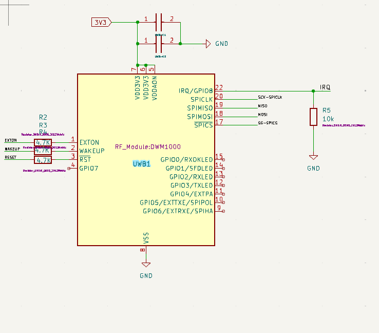
W5500 Ethernet Sheet Datasheet Link:
W5500 Chip Datasheet: https://cdn.sparkfun.com/datasheets/Dev/Arduino/Shields/W5500_datasheet_v1.0.2_1.pdf
ESP32-WROOM-32 Datasheet ://www.espressif.com/sites/default/files/documentation/esp32-wroom-32d_esp32-wroom-32u_datasheet_en.pdf
UWB-DWM1000 Datasheet: https://www.mouser.de/pdfDocs/dwm1000-datasheet-1.pdf


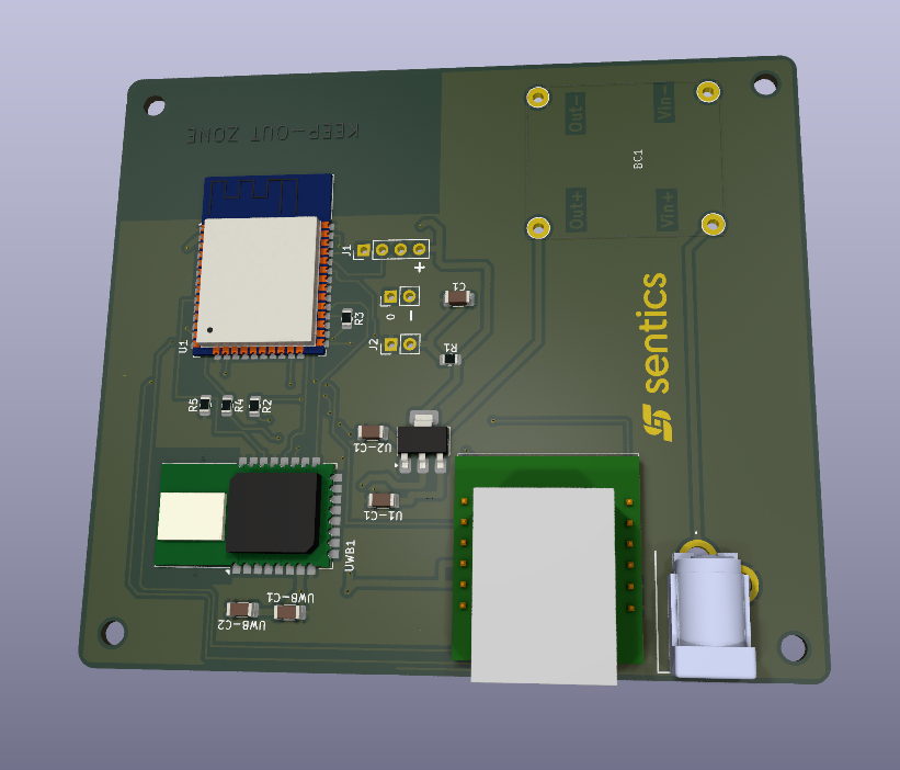
Hi I am sending you links of datasheet of all components and uploading schematics.You can take a look.I think there is issue in Ethernet Library i am only using ethernet lib and not ethernet2 and ethernet3.Can you please take a look at circuit and my code if there is any issue thanks
(Attachment Anchor POE DATA Final.rar is missing)
The W5500 is missing some bypass capacitors, the others look OK, I am assuming the values etc are correct. Why are you using two SPI busses? The middle schematic is not readable on my system. I am not familiar with the libraries but do they define the SPI pins and if so are they the correct ones. I have seen different declarations of the SPI pins in the past. It has been a while and I do not remember which library(s) had the problem.
I am using Two Separate SPI to avoid Data Collisions As i need both devices active at the same time so there might be a data collision. Both devices gets initialized that is UWB and W5500 but the UWB is not getting distance, If add delay for W5500 the UWB immediately Gets readings but after delay When W5500 tries to initialize it fails. The capacitors where I need to add the W5500 is proper ethernet shield all the required components are there thanks I will share the SPI Busses from ESP32 website

Also can you please check the code combination of W5500 and UWB may be there is issue in code combination thanks
does the Ethernet module work by itself in a separate program with no other devices connected?
have you tried EthernetESP32 library - note it requires ESP32 platform version 3 or higher - I have used it with both VSPI and HSPI
// ESP32/W5500 ethernet using HSPI interface

// W5500 SCK to HSPI_SCK GPIO14
// W5500 MOSI to HSPI_MOSI GPIO13
// W5500 MISO to HSPI_MISO GPIO12
// W5500 SCS to HSPI_CS GPIO15
// W5500 3.3V to ESP32 3.3V
// W5500 GND to ESP32 GND
Yes the module is working fine alone as it is initialized and I can get data from it can view it from wire shark. Can you please take look at the combination of code for uwb ans w5500 may be it’s blocking in one way or other
No i did not try with EthernetESP lib
If you have code using ethernetESP lib please can you share it
Thanks
W5500 using ESP32 HSPI helloServer example
// ESP32/W5500 ethernet using HSPI interface

// W5500 SCK to HSPI_SCK GPIO14
// W5500 MOSI to HSPI_MOSI GPIO13
// W5500 MISO to HSPI_MISO GPIO12
// W5500 SCS to HSPI_CS GPIO15
// W5500 3.3V to ESP32 3.3V
// W5500 GND to ESP32 GND

/*
 * HelloServer example from the ESP32 WebServer library modified for Ethernet.
 */

#include <EthernetESP32.h>
#include <WebServer.h>
#include <ESPmDNS.h>

W5500Driver driver(15);  // HSPI SS is GPIO15
//ENC28J60Driver driver;
//EMACDriver driver(ETH_PHY_LAN8720);

SPIClass hspi(HSPI);  // HSPI object used by W5500

WebServer server(80);

const int led = 13;

void handleRoot() {
  digitalWrite(led, 1);
  server.send(200, "text/plain", "hello from esp32!");
  digitalWrite(led, 0);
}

void handleNotFound() {
  digitalWrite(led, 1);
  String message = "File Not Found\n\n";
  message += "URI: ";
  message += server.uri();
  message += "\nMethod: ";
  message += (server.method() == HTTP_GET) ? "GET" : "POST";
  message += "\nArguments: ";
  message += server.args();
  message += "\n";
  for (uint8_t i = 0; i < server.args(); i++) {
    message += " " + server.argName(i) + ": " + server.arg(i) + "\n";
  }
  server.send(404, "text/plain", message);
  digitalWrite(led, 0);
}

void setup(void) {
  pinMode(led, OUTPUT);
  digitalWrite(led, 0);
  Serial.begin(115200);
  delay(2000);
  while (!Serial)
    ;
  driver.setSPI(hspi);        // specify driver SPI interface
  Ethernet.init(driver);      // initialise driver
  Serial.println("Initialize Ethernet with DHCP:");
  if (Ethernet.begin()) {
    Serial.print("  DHCP assigned IP ");
    Serial.println(Ethernet.localIP());
  } else {
    Serial.println("Failed to configure Ethernet using DHCP");
    while (true) {
      delay(1);
    }
  }
  if (MDNS.begin("esp32")) {
    Serial.println("MDNS responder started");
  }
  server.on("/", handleRoot);
  server.on("/inline", []() {
    server.send(200, "text/plain", "this works as well");
  });
  server.onNotFound(handleNotFound);
  server.begin();
  Serial.println("HTTP server started");
}

void loop(void) {
  server.handleClient();
  delay(2);  //allow the cpu to switch to other tasks
}
serial monitor output
Initialize Ethernet with DHCP:
  DHCP assigned IP 192.168.1.65
MDNS responder started
HTTP server started
PC we client

SPI (Serial Peripheral Interface) is a master-slave communication bus. As long as there is only one master and the chip selects are properly configured, collisions will not occur.