Bahij_mik:
Hey guys, can someone please give me a diagram how to connect a 5V pump to an outer source ( like a 9v wall wart) while controlling it through arduino Digital pin (HIGH LOW) ?
Wow this is way too complicated for me
Hey guys, can someone please give me a diagram how to connect a 5V pump to an outer source ( like a 9v wall wart) while controlling it through arduino Digital pin (HIGH LOW) ?
https://electroslab.com/collections/power-supplies/products/adapter-5v-1a
Are you going to use the 5v 1A power supply? If you use the 9V supply, how do you intend to get the 5v for the pump?
Do you know the current rating of the pump?
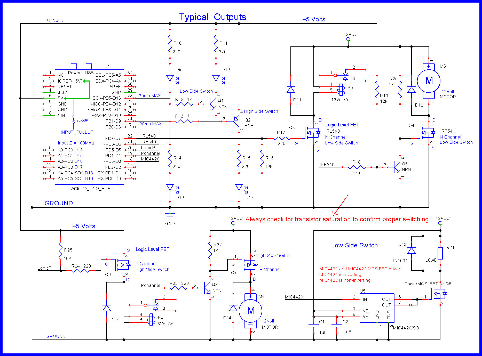
You will need a relay, transistor or logic mosfet to switch the pump on and off from the Arduino digital pin. Do you have any of these parts?
Do you have a mechanical toggle switch you could use to turn the pump on and off if you don't have one of the active parts and want to work on the other aspects of the program?
cattledog:
Are you going to use the 5v 1A power supply? If you use the 9V supply, how do you intend to get the 5v for the pump?Do you know the current rating of the pump?
You will need a relay, transistor or logic mosfet to switch the pump on and off from the Arduino digital pin. Do you have any of these parts?
Do you have a mechanical toggle switch you could use to turn the pump on and off if you don't have one of the active parts and want to work on the other aspects of the program?
Yes, i already have a power supply module which takes 6.5 to 12 V input -> $6.49 - Breadboard Power Supply Module 3.3V & 5V (Arduino & Raspberry Pi Compatible) - Tinkersphere
Current rating of pump is 130 to 220 mA, i do have transistors, relays, and diodes but no mosfet though.
Current rating of pump is 130 to 220 mA, i do have transistors, relays, and diodes but no mosfet though.
Any info on the stall current of the motor? If you have a multimeter, can you measure the resistance through the leads when the motor is not running?
Explain what you have for relays or transistors. I'm sure something will be suitable.
For on off control, the relay should be fine and if its a module, may be more simple for you to wire up than a transistor, gate resistor and flyback diode.
Regarding the power supply. I see
Max Current:
750mA at 6.5-8V Supply
530mA at 9V Supply
380mA at 10V supply
300mA at 11V supply
250mA at 12V supply
530 ma sounds marginal for all the loads that Nick_Pyner has listed.
NPN Transistor PN2222 and 5v relay, no info on stall current for the pump, is it necessary? The pump is pretty small.
NPN Transistor PN2222 and 5v relay, no info on stall current for the pump, is it necessary? The pump is pretty small.
If the running current is 200ma, the startup/stall current might be marginal for the PN2222. If you want to use it, measure the motor resistance to be sure. Do you have a multimeter?
Do you have specs on the relay? If its 5 or 10 amps at 30 vdc its well capable. There's no reason not to use it.
There are plenty of tutorials on how to hook up the relay.
Hello guys! So i used a relay and everything is working great when there is water pumping, but i am facing an irritating problem, which is the water pump is sucking air when the main container is empty, therefore the flow sensor’s pin wheel keeps turning giving false readings and by false i mean not in a small range that i can predict and rule out by code, just random numbers, any ideas if it’s possible to keep the air out of the equation? Like if i put another tube and kept the other tube that has the flow sensor on immersed in water so the air finds its way out ? Just like burping the car radiator?

Hi,
Put a float switch in the main container to indicate when the tank is low, and stop the pump before it sucks air.
Draw your circuit with pen and paper and post a picture of it .
Tom.. ![]()
Hey Tom, but one of the key elements in this project is that the flow sensor is the one that should detect if there is no more water and stop the pump, since that’s the only use of it ( i am not using it to find the amount of water that passed through it) thank you.
Yes. I have a similar situation and intend to make the same solution. When the water gets to the vent point, the pump has done virtually all its job, and you just need to ensure gravity will do what the pump hasn't. When there is just air, there shouldn't be any going through the sensor - or hardly any..
which is the water pump is sucking air when the main container is empty, therefore the flow sensor's pin wheel keeps turning giving false readings and by false i mean not in a small range that i can predict and rule out by code, just random numbers,
Please post the code you are using, and the readings you see with water, and the readings you see with air. How long have you waited to see if the air readings are different from the water readings? If the pump starts dry, does the sensor wheel spin when air is going through?
Hi,
Is the pump sucking water through the flow sensor, or pushing it through.
It sounds like you have a good flow sensor with low losses and even air being pumped will make it turn.
So how can you tell the difference fluid flow and gas flow?
Checking if flow media is there or not, is not the function of the flow meter. In your case you have flow media all the time, just its density changes.
Tom... ![]()
Hey guys, i am so sorry for the late replies but i was busy lately and didn’t have time to continue this project, today i actually found out the issue, i opened up the flow sensor and the wheel isn’t spinning from air afterall!! It seems when the pump is turning on something weird is happening to the arduino therefore the random values because only when i turn the pump on weird things happen, the pump is connected to another power supply(not the arduino) with a relay to control it through arduino ( turn it off and on), as soon as i turn it on the random values start rolling, its like the flow meter is surging or i don’t know, any ideas what should i do to solve this issue?

Here is what’s happening.
Try and disconnect the pump from the relay to see which is producing the interference.
Do you see the random values when you turn the relay on without the pump connected?
Hey man, what i did now is i directly connected the pump to the power source without the relay and i still got the random values!!! How is this possible? The pump is literally out of the equation and the flow meter is disassembled!
I think the pump is a source of radiated EMI which is getting into the interrupt lead. Previously you said that when the pump was under water you saw stable flow values. Is that still the case?
If you remove the wire from the flow meter to the interrupt pin do you see the random values when the pump is running?
Man i think i am going to lose my mind, i disconnected EVERYTHING and only connected the flow sensor which is not even assembled to the arduino, and the pump from an outer source and i even disconnected the pipes so that there is connection between them at all! And still i am getting the random numbers once i connect the pump to the wall( with no connection to arduino AT ALL) what is going on? Is my arduino haunted?