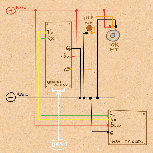
i have a 10k potentiometer set up with an arduino micro :
• pot + terminal is connected to the +5v rail, which is connected to the arduino micro 5v pin
• pot - terminal is connected to the shared ground rail (connected to arduino ground)
• pot signal terminal is connected to arduino A0 pin, with a 100nF capacitor between the signal and ground (for signal cleanup)
this reads cleanly into the arduino serial monitor on my laptop if i sweep the pot knob, i'm software-filtering so only value changes greater than 5 are captured.
as soon as i connect the sparkfun/robertsonics wav trigger 5Vin pin to the shared 5v rail, i get signal chatter in the serial monitor, value changes up to 40 or so all of a sudden in a constant, random stream. pulling the wav trigger 5v connection from the +5v rail stops the chatter. i can turn the knob and the value changes accordingly, but then of course that random +/- 40-or-so jittering hovers around the new "real" pot value reading.
i have the wav trigger's 5v jumper gap bridged, and i'm using the pre-installed ftdi header pins for the ground and 5vin connections on the wav trigger.
this is all powered via USB into the arduino (currently via laptop, eventually from a 1A or so wall adapter.) i was thinking about cutting into the usb cable before it reaches the arduino and split out the +5v to feed the arduino and the wav trigger, but would be much more elegant to use the 5v from the arduino.
why am i getting this chatter? was really hoping to power the wav trigger via the arduino/shared rail for my project...
thanks!
added diagram to original post...
as soon as i connect the sparkfun/robertsonics wav trigger 5Vin pin to the shared 5v rail, i get signal chatter in the serial monitor, value changes up to 40 or so all of a sudden in a constant, random stream.
So how much current does this trigger take? It sounds like it is taking more than the Arduino can give despite what you think. Can you post a link to it?
pulling the wav trigger 5v connection from the +5v rail
Never ever mess about with wiring while the power is attached, it is a great way to damage things.
Grumpy_Mike:
So how much current does this trigger take? It sounds like it is taking more than the Arduino can give despite what you think. Can you post a link to it?
certainly! very cool little device!
robertsonics own product page :
http://robertsonics.com/wav-trigger/
the user guide :
http://robertsonics.com/wav-trigger-online-user-guide/
( it states here that it can draw 200mA if using the built in audio amplifier and driving speakers. i was hoping that even with that stated extreme it was a reasonable amount within the 500mA allowance of USB power, with the intention of much less current draw in my final implementation. i'm planning on using the built-in line out and keeping the amp disabled, so the wav trigger should be drawing a good amount less than 200mA under my final usage conditions, and especially at this minimal testing point that i'm not using any audio or SD card reading on the unit )
sparkfun product page :
sparkfun hookup guide :
https://learn.sparkfun.com/tutorials/wav-trigger-hookup-guide-v11?_ga=2.116664262.1545387447.1609630129-583404173.1605949462
Grumpy_Mike:
Never ever mess about with wiring while the power is attached, it is a great way to damage things.
i apologize, yes indeed i should have chosen my words more carefully. i unplugged the arduino usb before attaching/pulling the wav trigger +5v wire/ground and then replugged to reboot everything and observe the serial monitor on laptop.
oh one more link, here's the page where it describes the power hookup that i'm attempting. i'm using an arduino micro (they reference an uno), but that shouldn't be a problem.
(the "extra credit" section right above the keyboard sampler tutorial) :
https://robertsonics.com/help/
Thanks for that.
I can't see anything wrong with the instructions you are following. In these sorts of cases the problem is normally in how you are implementing them.
First thing I would check is to see what is happening in terms of the if the Arduino is crashing or restarting. So put something in the setup function that prints out something to the terminal or flashes the built in LED for a short time. Have nothing in the loop function at this stage. Have no dealings with the wav trigger board at this stage.
Next can you measure the voltage on the 5V input to the wav trigger board and see if it is going up and down. A DVM might not react fast enough to show this as they generally only take three samples per second. The way to see this is to use an oscilloscope if you have one. Maybe you can put an LED and resistor on the 5V line.
Then add the initialisation of the wav trigger board to the setup function.
If this is clear slowly add functionality to the software until you run into problems.
Also a clear photograph showing your wiring would help.
photographs of the wiring (please let me know if alternate angles, etc. would be useful) :


ok, the arduino setup doesn't seem to have a reset / crash issue. only a single monitor display line showing with a serial line placed in setup. also, with the pot code and wiring added, no errant pot readings, no changes in the monitor unless i deliberately turn the pot knob. i do get a tiny amount (1-2 steps) of value "drift" on the pot reading without the capacitor and the software filtering in place, but that is to be expected.
w/o any wav trigger code or wiring additions, it looks to behave correctly.
hehe no i have not yet earned my oscilloscope wings, so multimeter it is unfortunately.
without adding any wav trigger stuff, LED test seems good (5v rail -> resistor -> LED -> ground rail), no noticeable flicker or dimness or anything like that.
multimeter reading voltage from +5v rail wire going to wav trigger is 5.00-5.05v, without much visible fluctuation. didn't see it dip below 5.00v.
whether or not the wav trigger library and init stuff is in the arduino sketch code, the random reading stream problem doesn't occur until i have the wav trigger connected to the 5v rail. without that connection made, whether or not the wav trigger code is in the sketch, the pot reading is clean and deliberate, no erratic readings.
tested the voltage of 5vin pin connected to the 5v rail with the wav trigger running, it is ~4.86 without much visible change in the multimeter readout.
some kind of feedback loop happening?
Can you try it with the wav trigger powered up to 5V but with the TX and RX lines disconnected.
hello yes i tried that, no change in behavior 
I would not use crocodile clips to connect that pot. They slip easily when moved and depending on the pot’s position shorting the wiper to a rail could burn out your pot.
I think it is time you posted your code now.
Edit closer look at the photo of the TX and RX lines from your micro. Are you sure you are not connecting to the reset pin? Seeing as the micro doesn’t cover all the pins, it looks like you are missing three at the end and one that is missing is the TX pin.
ok, first here's the pot monitoring only :
int trackPin_VolPot_1 = A0;
int trackPin_VolPot_1_PrevState = 0;
int trackPin_VolPot_1_CurrentState = 0;
bool track1VolSet = false;
int potValChangeTolerance = 5;
void setup() {
  Serial.begin(9600);
  while (!Serial) ;
  Serial.println("USB Serial Begin");
  readVolPots();
}

void loop() {
  readVolPots();
}

void readVolPots(){
  // track 1 vol pot
  trackPin_VolPot_1_CurrentState = analogRead(trackPin_VolPot_1);
  int allowTrack1VolPotChangeResult = 0;
  if( trackPin_VolPot_1_PrevState != trackPin_VolPot_1_CurrentState ){
    if( trackPin_VolPot_1_CurrentState == 0 ){
      allowTrack1VolPotChangeResult = 1;
    }
    if( trackPin_VolPot_1_CurrentState < (trackPin_VolPot_1_PrevState - potValChangeTolerance) ||
      trackPin_VolPot_1_CurrentState > (trackPin_VolPot_1_PrevState + potValChangeTolerance) ){
      allowTrack1VolPotChangeResult = 1;
      if( trackPin_VolPot_1_CurrentState <= 5 ){
        trackPin_VolPot_1_CurrentState = 0;
      }
    }
  }
  if( !track1VolSet ){
    allowTrack1VolPotChangeResult = 1;
    track1VolSet = true;
  }
  if( allowTrack1VolPotChangeResult == 1 ){
    trackPin_VolPot_1_PrevState = trackPin_VolPot_1_CurrentState;
    Serial.print( "pot val = " );
    Serial.print( trackPin_VolPot_1_CurrentState );
  }
  // Delay 30 msecs
  delay(30);
}
and here we have the bare-bones wav trigger stuff added (only checking for wav trigger firmware version and basic, init comms). the pot remapping stuff is specific to the wav trigger's expected volume range control, i left it in for posterity :
#include <wavTrigger.h>
wavTrigger wTrig;
char gWTrigVersion[VERSION_STRING_LEN];    // WAV Trigger version string

int trackPin_VolPot_1 = A0;
int trackPin_VolPot_1_PrevState = 0;
int trackPin_VolPot_1_CurrentState = 0;
bool track1VolSet = false;
int potValChangeTolerance = 5;
int trackVolPotOriginalMin = 0;
int trackVolPotOriginalMax = 1023;
int trackVolPotMapMin = -70;
int trackVolPotMapMax = 10;
void setup() {
  Serial.begin(9600);
  while (!Serial) ;
  Serial.println("USB Serial Begin");
  readVolPots();
  // If the Arduino is powering the WAV Trigger,
  // we should wait for the WAV Trigger to finish reset
  // before trying to send commands.
  delay(1000);
  // WAV Trigger startup at 57600
  wTrig.start();
  delay(10);
  wTrig.setReporting(true);
  // Allow time for the WAV Trigger to respond with the version string
  delay(100);
  // If bi-directional communication is wired up,
  // then we should by now be able to fetch the version string
  if( wTrig.getVersion(gWTrigVersion, VERSION_STRING_LEN) ){
    Serial.print("gWTrigVersion = ");
    Serial.println(gWTrigVersion);
  }else{
    Serial.println("no wav trig comms!");
  }
}

void loop() {
  readVolPots();
}

void readVolPots(){
  // track 1 vol pot
  trackPin_VolPot_1_CurrentState = analogRead(trackPin_VolPot_1);
  int allowTrack1VolPotChangeResult = 0;
  if( trackPin_VolPot_1_PrevState != trackPin_VolPot_1_CurrentState ){
    if( trackPin_VolPot_1_CurrentState == 0 ){
      allowTrack1VolPotChangeResult = 1;
    }
    if( trackPin_VolPot_1_CurrentState < (trackPin_VolPot_1_PrevState - potValChangeTolerance) ||
      trackPin_VolPot_1_CurrentState > (trackPin_VolPot_1_PrevState + potValChangeTolerance) ){
      allowTrack1VolPotChangeResult = 1;
      if( trackPin_VolPot_1_CurrentState <= 5 ){
        trackPin_VolPot_1_CurrentState = 0;
      }
    }
  }
  if( !track1VolSet ){
    allowTrack1VolPotChangeResult = 1;
    track1VolSet = true;
  }
  if( allowTrack1VolPotChangeResult == 1 ){
    trackPin_VolPot_1_PrevState = trackPin_VolPot_1_CurrentState;
    int track1VolPotRemap = map(trackPin_VolPot_1_CurrentState, trackVolPotOriginalMin, trackVolPotOriginalMax,trackVolPotMapMin, trackVolPotMapMax);
    Serial.print( "pot val = " );
    Serial.print( trackPin_VolPot_1_CurrentState );
    Serial.print( " --- " );
    Serial.println( track1VolPotRemap );
  }
  // Delay 30 msecs
  delay(30);
}
sorry the original close-up of the arduino is misleading because of the camera optics. it's raised above the breadboard by some header strips so the pins on the arduino look out of alignment with the breadboard. let me know if you need any more images to better depict alignment!
Come on. You are not telling me that this image,
is the same thing as this image but taken from a different angle.
I know about lens distortions but these are two completely different things.
Can you clear one thing up. When the 5V is connected to the .wav trigger board you get this resetting action no matter what software you have. That is like software that just blinks an LED and nothing more?
yep, it's the same thing. here's another angle. the hovering phone lens was very close and the different height planes caused from the header strips on the breadboard made the holes look misaligned, as the arduino board was inadvertently "enlarged to show texture"  .
.

i'm not really sure what you mean in your second question but i will try to answer. yes even with the most basic, init-only, firmware-retrieval wav trigger commands, or even NO wav trigger include/scripting in the arduino sketch, the wav trigger connected to the 5v rail coming from the arduino's 5v pin is resulting in the pot pin read noise. throughout the serial monitor noise observation, neither the arduino nor the wav trigger actually seem to be resetting beyond the initial startup process (the wav trigger hardware shows a solid led and then 3 blinks at reset, then a regular, slower auto-blink interval while running).
i have taken an alternate, sadly less elegant approach that seems to be working for me in it's current, fledgeling state. i am running the USB from laptop into a breakout board, from there jumping all of the USB cable wires to another cut USB cable running into the arduino, with the power split at the breakout board and jumped to the wav trigger. i also bumped the sketch pot value change tolerance from 5 to 7 steps (the noise was previously far more varied in the step range, unreasonably for actual reading usage). i now have none of the previous noise with one or more pots connected as before to the arduino/rails. we'll see if this method continues to work out as i expand the circuit!