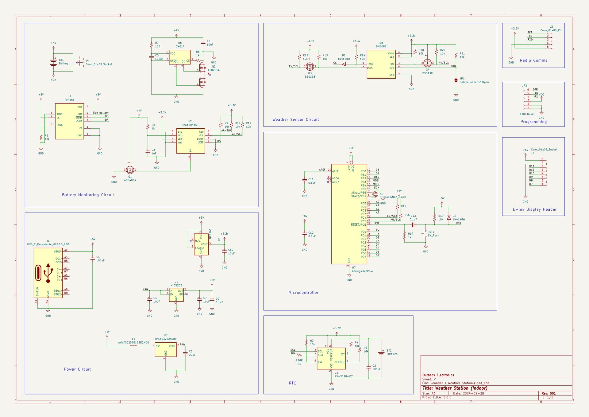
I am building a PCB for a weather station, I'm hoping before I close off all the unneeded connections, someone could have a look and see if anything pops out at them? Anything you might add? I know most weather stations have speakers, but I can't decide if that is actually useful or not. Do I actually need input buttons if nothing ever gets changed on it?
Why is there an RTC in the battery monitoring circuit? EDIT: I see you moved it now.
What is the MAX17034 chip for?
I think my most important piece of feedback would be to simplify the whole circuit by removing the need for 5V. If you run everything at 3.3V you can remove the MCP161, the crystal & caps for the atmega (use it's 8MHz internal oscillator), the MOSFETs for level shifting and maybe other components.
1 Like
This is for monitoring the lithium battery voltage (not so much for exact voltage, more for "Do I need to charge this again?")
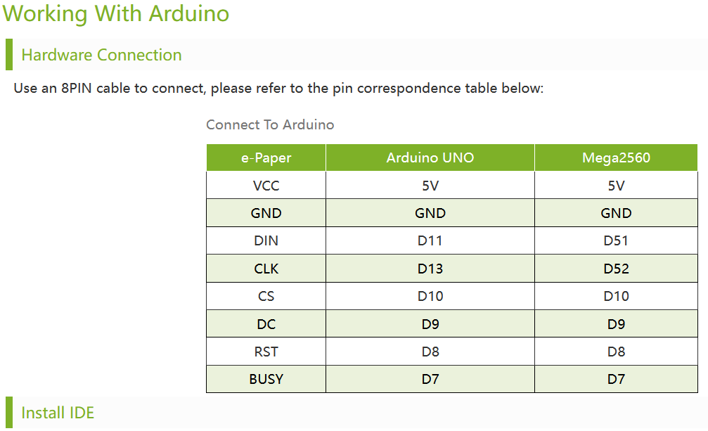
A couple of the chips use 5v such as the charging chip. Plus the USB is 5v, so it'll be there in some form regardless. Also the e-ink display says 5v on the waveshare website.
If I could completely remove 5v, it would run more efficiently and the battery would last longer I guess.
Why not just connect the battery voltage through a voltage divider to an atmega analog input?
The charging chip only needs that when USB is connected, in which case it gets the 5V from USB. You don't need to make 5V using a boost converter. What else needs 5V?
Post a link to that. Something as modern as an e-ink display probably runs at 3.3V or less. That table is probably just assuming the Arduino will always be a 5V Arduino.
1 Like
I think you are correct. I've been looking at it, the raspberry pi connections ask for 3.3v.
That chip outputs I2C data, means it works with a prebuilt library just for this.
Genius. I guess I'm gonna kick all the 5v off the board!
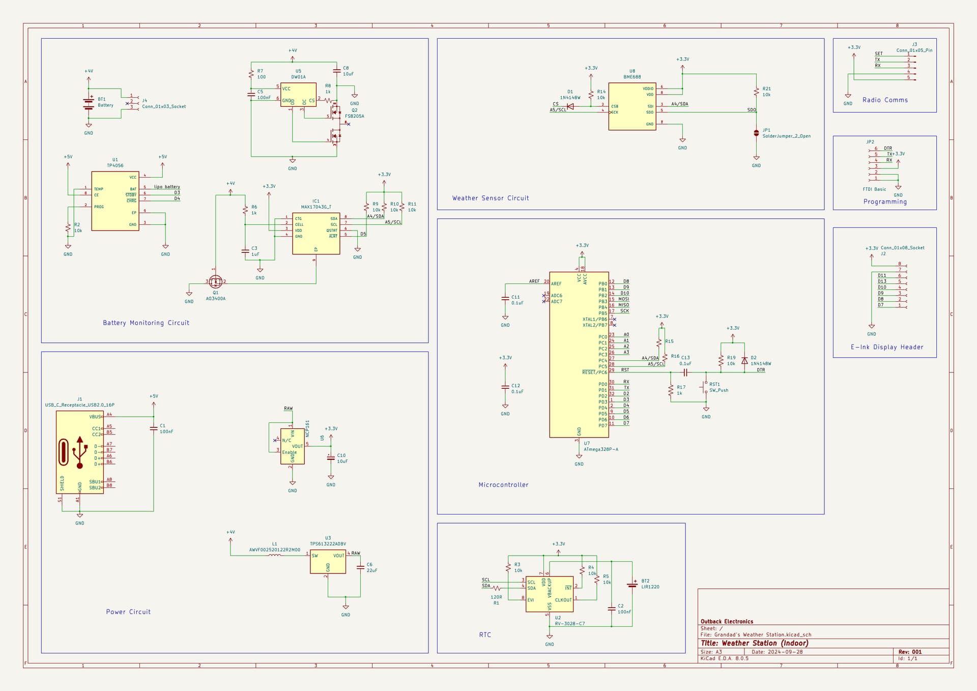
So this is what I've got now. What do you think?
Just got to remember to program it with a 3.3V FTDI module or stuff will go pop!
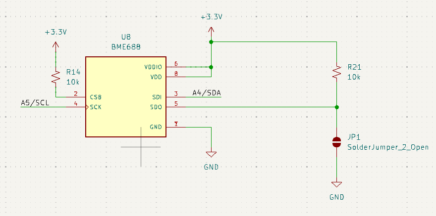
Since I'll be using it in I2C mode, I can change this:

to this:
Is that correct?
Also, as the ATMEGA328PB is basically a drop in replacement (at least for the schematic) I'll probably swap to that.

So it should look something like this.
It's overkill. You only need:
Remember that each component you add to a circuit makes it more likely that you will never get it to work, and even if you do, more likely that something will fail eventually.
Still seems over-complicated to me. Those 2 chips in the "power circuit" section. What are they for? Do you really need them?
What are the diode and the 1K resistor for on the DTR/RESET line?
What are R14 and R21 for? And the solder jumper?
R14 is to not leave that pin floating.
R21 and the solder jumper are so I can change the I2C address if necessary.
Those are for the protected battery charger. I do not want to remove them as I need USB charging, and wish to do so safely.
That is true, but you also need enough components to perform the right things the right way. I would rather monitor the battery with I2C than with an analogue input as the MAX17043 already sets up the interrupts (ALERT pin) for low voltage and already has a library to do all the functions needed.
Nice project. But I agree that you can still simplify it a bit more.
Yes, but the TP4056, the DW01A and one mosfet (not in the schematic below), should be enough. They are designed to protect the battery and manage the charging.

If you plan to charge the battery when the device is on, then you need an additional p-channel mosfet, you can google for the details, or we can check.
You could additionally monitor the battery level with an analog pin (the usual way) from the MCU, but what will you do more in case of low voltage? Depends on your requirements, of course, but the TP4056 will already light the red led to indicate low battery and green for charged, disconnect when needed, etc.
Another thing that you could simplify is the boost converter, I think that you don't need it. Is true that the battery will go below 3.3V, but it will be just at the very end. And all in all you will waste more power boosting and dropping the voltage all the time, than squeezing the last 2%. See the tipical discharge curve:

You will be discharging it slowly, so more like the black line.
And even when it happens could be that the LDO will pass the voltage down to 3.0V, you could test it, and I think that your devices will work fine at 3V or less, check it.
Your schematic looks good and I think that you have analyzed the options and designed it carefully. Just one recommendation to make it easier to follow, you should connect some of the isolated modules with wires instead of with labels. Maybe not everything but at least all the power section. Otherwise for one label I have to scan all the schematic to find where is it going to.
For example, the battery connector, USB, TP4056, DW01A, mosfets and LDO should be connected together from left to right with wires. And at the end in the right side you get just the 3V3 output label, used in the rest of the circuit.
I use the pre built modules all the time, the battery goes flat without ever lighting an LED.
On mine, the red LED lights when charging, and the blue LED lights when it is charged. That's it.
Not sure what you mean by that, I run things frequently while charging with these modules, never added a mosfet, and never had an issue.
That's true.
Can it not be directly connected to 3.3V?
Why would that ever be necessary, for your weather station?
Then for what purpose are the TP4056 and DW01A?
But your code must check that alert pin and take appropriate action when needed. It can do that just as easily with an analog input, can't it?
Not sure what two chips you mean, the two I see are TP4056 and DW01A.
Probably isn't unless something else connected to I2C has the same address.
Yes, but far more messy.
Ok, I'm not sure, maybe you are right. I think that the protection level is below, at about 2.8V. But maybe you can adjust it, check the datasheet.
Some batteries have over/under charge protection, but in general if the device is on the TP4056 will not detect properly when it is full and will overchange it. Here is explained: https://www.instructables.com/Load-Sharing-Use-Solar-Panel-Safely-With-TP4056/
1 Like
Unless I missed it, I didn't see the datasheet specify, so I;'m copying that from the Adafruit schematic. They have it connected to 3.3V through a resistor.

It is not.
Bettor read the datasheet and appnotes.
I use it frequently, as I stated, as far as the schematic is concerned, it is basically a drop in replacement. There are only four extra pins, not a big deal for the schematic.
Better read the whole sentence before hitting reply ![]()
![]()
They are in the "battery monitoring" section. I am taking about the "power circuit" section
Looking again, I see one of them is a 3.3V voltage regulator. This was a different model before, I think?
I don't see any connector for additional i2c devices on your schematic, so how would some other device with same address be connected?
I did not pay an attention to whole topic.
R17! It will keep the RESET low permanently.
C13 - what should be the purpose? It is probably taken from UNO R3. Check it again.
Sorry, my bad. I wasn't thinking clearly.
There had been three chips - a 5v regulator, a 3.3v regulator, and a boost chip. Now it is only 3.3v regulator, and a boost chip, though as @stonemk suggested, the boost chip probably isn't necessary either.