Weird PWM behaviour of Arduino Uno v3

Hellow everyone,

I recently found a weird behaviour of my arduino uno.

I'm switching a 1kHz PWM signal on pin 3, everything workes.
Then the duty cycle reaches 250 = 100%, after that the duty cycle is switched off = 0;

After a 1sec delay, the pwm signal is switched on again, the very first pwm impulse is incorrect.
The duty cycle is too long, and the timing is wrong.

Oscilloscope screenshots attached:


Since I set up a huge project with several hundrets lines of code, I summarized a working code that produces the very same output.

#define PWM_PIN 3   // analog output pin for 1kHz PWM Signal
#define PWM_CS 250  // PWM Clock Select for prescaler 250 -> 100% +Duty


void setup() {
  TCCR2B = TCCR2B & 0b11110000 | 0b00001011;  // modifying timing register to double the PWM freq. from 490Hz to 980Hz
  OCR2A = 0xFA;                               // fine tuning prescaler, slightly shorten pwm period from 256 to 250 steps to achieve exactly 1kHz

  pinMode(PWM_PIN, OUTPUT);
}

void loop() {
  analogWrite(PWM_PIN, 5);
  delay(250);
  analogWrite(PWM_PIN, 250);
  delay(250);
  analogWrite(PWM_PIN, LOW);
  delay(1000);
}

pwm_test.ino (590 Bytes)

Kind regards

The 100% point in the duty cycle is 255, not 250.

Dear Grumpy_Mike

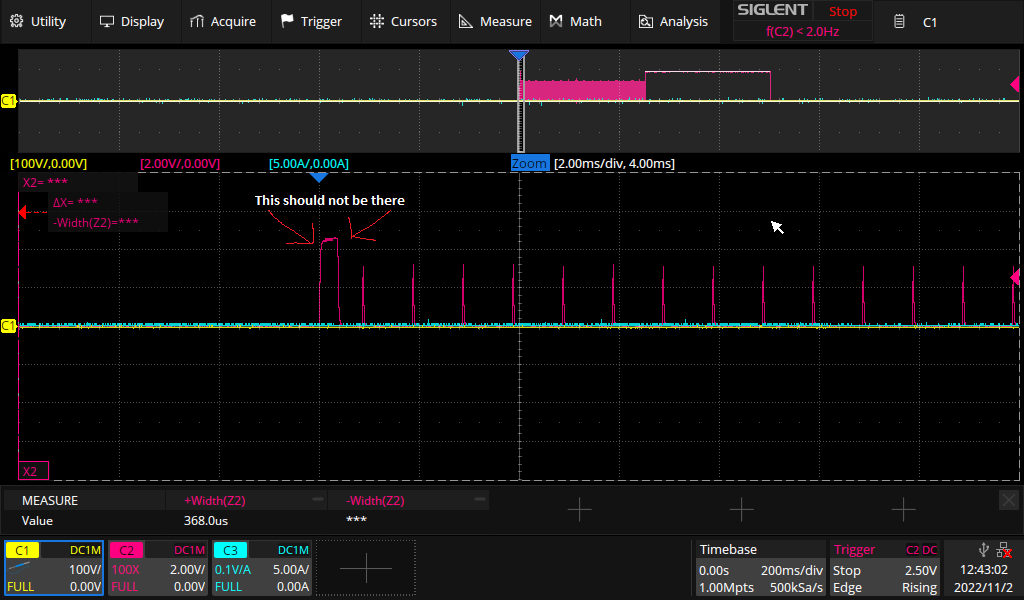
since I modified the timing register and the prescaler,
the 100% point in the duty cycle is 250, as stated in my code posted.

TCCR2B = TCCR2B & 0b11110000 | 0b00001011;  // modifying timing register to double the PWM freq. from 490Hz to 980Hz
OCR2A = 0xFA;                               // fine tuning prescaler, slightly shorten pwm period from 256 to 250 steps to achieve exactly 1kHz

This was done to archive exactly 1kHz PWM frequency, but that's not what my post is about at all.

Kind regards

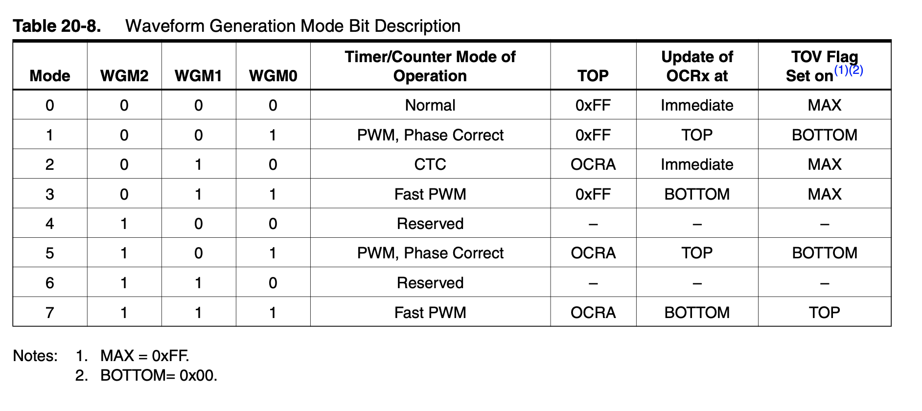
OCR2A has nothing to do with prescaler. It is compare value of Timer2 channel A. It will be changed any time when you use analogWrite() on Timer2 A channel

see the analogWrite() sourcecode:

void analogWrite(uint8_t pin, int val)
{
	
	pinMode(pin, OUTPUT);
	if (val == 0)
	{
		digitalWrite(pin, LOW);
	}
	else if (val == 255)
	{
		digitalWrite(pin, HIGH);
	}
	else
	{
		switch(digitalPinToTimer(pin))
		{
			// .... other timers code skipped...

			#if defined(TCCR2A) && defined(COM2A1)
			case TIMER2A:
				// connect pwm to pin on timer 2, channel A
				sbi(TCCR2A, COM2A1);
				OCR2A = val; // set pwm duty
				break;
			#endif
1 Like

It's awkward to interpret your code with the mix of binary and arduino defaults. I'm guessing you're going for WGM Mode 3 with PWM on Pin3/OCR2B?

If you are bit-twiddling the WGM2 bit in TCCR2B, I'd go ahead and set the rest of the registers like TCCR2A and TCNT2, and instead of using analogWrite(...) I'd use OCR2B.

I didn't dig into it, but I'd suspect that the digitalWrite() from analogWrite(PWM_PIN,LOW) twiddles some of the registers, and lets TCNT2 count above OCR2A, giving you a one-shot behavior when you re-enable PWM.

1 Like

Thanks DaveX,

that was indeed the case.
I'm now using OCR2B instead of analogWrite.
Had to rewrite some of my code, but the one shot behaviour is now gone.
I needed to get away from analogWrite() and learn how to properly use the registers.

Kind regards!

1 Like

But see, it was. :stuck_out_tongue:

3 Likes

This topic was automatically closed 180 days after the last reply. New replies are no longer allowed.