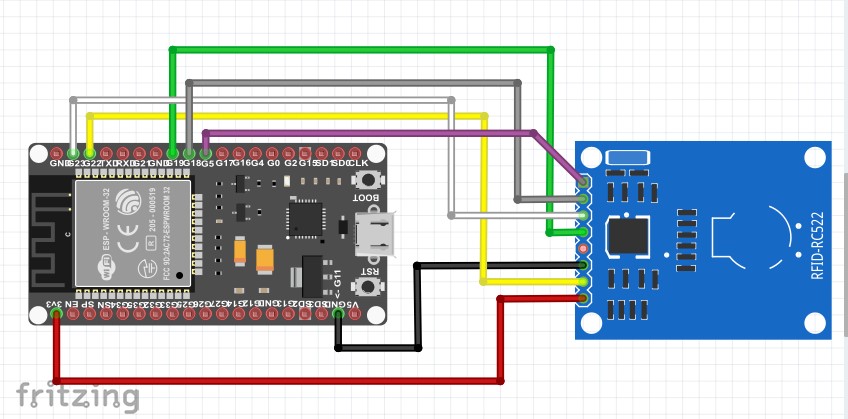
I am trying to get the WEMOS S2 MINI to drive a TFT and have run into some basic problems with the SPI.
This board uses an ESP32-S2 with 4MB FLASH and 2MB PSRAM.
I am using ESP32 board core 2.0.1-RC1 and Arduino 1.8.15
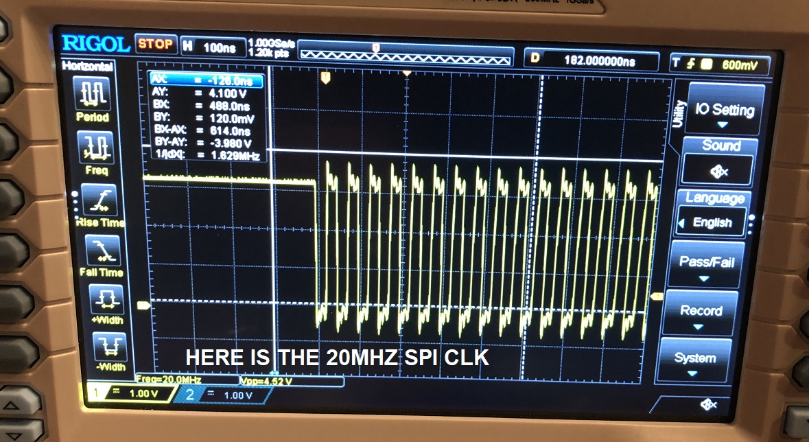
The program below produces a 20MHz 3.3V clock on pin 36 but the MOSI data on pin 35 is only about 1V peak to peak. I am measuring this with a 200MHz Rigol scope.
When I just toggle pin 35 in a loop as a regular output I get a full 3.3V square wave as expected. So the problem appears to be something with the SPI setup.
VDD_SPI measures at 3.3V. I have tried this on several of these S2 Mini boards and the SPI CLK is there but MOSI is not or very low,
I have tried the clock at 1MHz, 20MHz and 40MHz and get the same thing. Clock looks fine, MOSI is low voltage or not there.
Any suggestions would be appreciated. Thanks, Bill
I thought I would add some images to show what I am seeing on the ESP32-S2 WEMOS S2 MINI SPI lines. Note the 1V MOSI SIGNAL and the 3.3V SCLK. I did add a 10K pull-up on the MOSI GPIO and it did not change the signal.
I wrote a second program to try to show the MOSI and digitalWrite on the same GPIO 35 on the same scope shot. The program, in a loop, initiates the spi, starts a transaction, writes out the data, ends the transaction and releases the SPI. Then it sets up GPIO 35 and toggles it ON and OFF 4 times. You can see the jump from 1V on the MOSI to 3.3V on the digitalWrite. There is another level of weirdness going on. It appears the SPI MOSI sometimes ends low, sometimes high. When it ends high, the digitalWrite low only goes down to 1V. I don't know why. Any guesses or suggestions would be appreciated. Here is the webpage for the WEMOS S2 Mini: https://www.wemos.cc/en/latest/s2/s2_mini.html
Here is the complete program:
Yes, I did get it working finally but I don't quite remember what the issue was. I will try to get back to you today after I look thru my notes. I absolutely did get it driving an SPI based LCD.
SPI0 and SPI1 are used internally to access the ESP32-S2’s attached flash memory. Both controllers share the same SPI bus signals, and there is an arbiter to determine which can access the bus.
SPI2 and SPI3 are general purpose SPI controllers. They are open to users. SPI2 and SPI3 have independent signal buses with the same respective names. SPI2 has 6 CS lines. SPI3 has 3 CS lines. Each CS line can be used to drive one SPI slave.