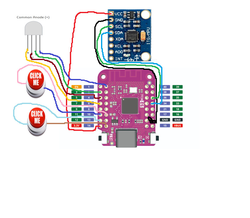
Hardware:
Esp32 s2 mini (wemos clone board)
GY-521 gyro
2x buttons
1 rgb led
thats it
I know this code is unoptimized cause i wrote it (mostly copy and paste anyway). I was wondering how i could optimize it, basically all this does is read a mpu6050 and send the data through udp to a udp server i have running on my pc. It works execpt it overheats pretty fast, its not efficent and I'd like to fix that. Please help ![]()
#include <Wire.h>
#include "I2Cdev.h"
#include "MPU6050_6Axis_MotionApps20.h"

#include <WiFi.h>
#include <WiFiUdp.h>

MPU6050 mpu;

#define LED_PIN 15
#define BUTTON1 14
#define BUTTON2 10

// Wifi
int status = WL_IDLE_STATUS;
char ssid[] = "myWifiSsd";
char pass[] = "superSecretPassword";
int port = 5468;
IPAddress ip(im,not,getting,doxxed);

WiFiUDP Udp;

// Gyro stuff
float RateRoll, RatePitch, RateYaw;
float AccX, AccY, AccZ;
float AngleRoll, AnglePitch;
float LoopTimer;
uint8_t devStatus;
uint16_t packetSize;
uint16_t fifoCount;     // count of all bytes currently in FIFO
uint8_t fifoBuffer[64];

Quaternion q;           // [w, x, y, z]         quaternion container
VectorInt16 aa;         // [x, y, z]            accel sensor measurements
VectorInt16 aaReal;     // [x, y, z]            gravity-free accel sensor measurements
VectorInt16 aaWorld;    // [x, y, z]            world-frame accel sensor measurements
VectorFloat gravity;
float ypr[3];

float axZero = 0;
float ayZero = 0;
float azZero = 0;

// Offset stuff
int16_t ax, ay, az, gx, gy, gz;

int buffersize=1000;
int acel_deadzone=8;
int giro_deadzone=1;

int mean_ax,mean_ay,mean_az,mean_gx,mean_gy,mean_gz,state=0;
int ax_offset,ay_offset,az_offset,gx_offset,gy_offset,gz_offset;

void setup() {
  Serial.begin(57600);

  status = WiFi.begin(ssid, pass);

  delay(10000);

  Udp.begin(port);

  //Buttons
  pinMode(12, OUTPUT);
  pinMode(11, OUTPUT);
  pinMode(15, OUTPUT);
  pinMode(14, INPUT_PULLUP);
  pinMode(10, INPUT_PULLUP);

  // LED
  pinMode(1, OUTPUT);
  pinMode(3, OUTPUT);
  pinMode(5, OUTPUT);
  pinMode(7, OUTPUT);

  digitalWrite(5,HIGH);

  digitalWrite(1,HIGH);
  digitalWrite(5,HIGH);
  digitalWrite(7,HIGH);

  digitalWrite(11,LOW);
  digitalWrite(15, HIGH);
  digitalWrite(15, LOW);


  Wire.begin(33,35);
  Wire.setClock(400000);

  mpu.initialize();

  Serial.println(F("Testing device connections..."));
  devStatus = mpu.dmpInitialize();
  Serial.println(mpu.testConnection() ? F("MPU6050 connection successful") : F("MPU6050 connection failed"));

  while(digitalRead(14)!=LOW){
    digitalWrite(3,LOW);
    digitalWrite(7,LOW);
    delay(1000);
    digitalWrite(3,HIGH);
    digitalWrite(7,HIGH);
    delay(1000);
  }
  digitalWrite(3,HIGH);
  digitalWrite(7,HIGH);

  delay(200);

  digitalWrite(3,LOW);

  Serial.println("\nStarting offset calibration...\n");

  // Reset offsets
  mpu.setXAccelOffset(0);
  mpu.setYAccelOffset(0);
  mpu.setZAccelOffset(0);
  mpu.setXGyroOffset(0);
  mpu.setYGyroOffset(0);
  mpu.setZGyroOffset(0);

  Serial.println("Reading sensors for first time...");
  meansensors();
  delay(200);

  Serial.println("\nCalculating offsets...");
  calibration();
  delay(200);

  meansensors();
  Serial.println("\nFinished calibration!\n");

  Serial.print("\nOffsets:\t");
    Serial.print(ax_offset);
    Serial.print("\t");
    Serial.print(ay_offset);
    Serial.print("\t");
    Serial.print(az_offset);
    Serial.print("\t");
    Serial.print(gx_offset);
    Serial.print("\t");
    Serial.print(gy_offset);
    Serial.print("\t");
    Serial.println(gz_offset);

  mpu.setXAccelOffset(ax_offset);
  mpu.setYAccelOffset(ay_offset);
  mpu.setZAccelOffset(az_offset);
  mpu.setXGyroOffset(gx_offset);
  mpu.setYGyroOffset(gy_offset);
  mpu.setZGyroOffset(gz_offset);

  digitalWrite(3,HIGH);

  while(!digitalRead(10)==LOW){
    digitalWrite(1,LOW);
    delay(1000);
    digitalWrite(1,HIGH);
    delay(1000);
  }
  if (devStatus == 0) {
    // Calibration Time: generate offsets and calibrate our MPU6050
    mpu.CalibrateAccel(6);
    mpu.CalibrateGyro(6);
    mpu.PrintActiveOffsets();
    // turn on the DMP, now that it's ready
    Serial.println(F("Enabling DMP..."));
    mpu.setDMPEnabled(true);

    // get expected DMP packet size for later comparison
    packetSize = mpu.dmpGetFIFOPacketSize();
  } else {
        // 1 = initial memory load failed
        // 2 = DMP configuration updates failed
    Serial.print(F("DMP Initialization failed (code "));
    Serial.print(devStatus);
    Serial.println(F(")"));
  }
  Serial.println(F("DMP Enabled"));

  delay(100);
  digitalWrite(1,LOW);
  digitalWrite(3,LOW);
  digitalWrite(7,LOW);
}
void loop() {
  if (mpu.dmpGetCurrentFIFOPacket(fifoBuffer)) {
    mpu.dmpGetQuaternion(&q, fifoBuffer);
    mpu.dmpGetGravity(&gravity, &q);
    mpu.dmpGetYawPitchRoll(ypr, &q, &gravity);
    Serial.print("ypr\t");
    Serial.print((ypr[0] * 180/M_PI)-axZero);
    Serial.print("\t");
    Serial.print(((ypr[1] * 180/M_PI)-7)-ayZero);
    Serial.print("\t");
    Serial.println((ypr[2] * 180/M_PI)-azZero);

    // Wifi data transmit (UDP)
    String message = "1," + String((ypr[0] * 180 / M_PI) - axZero) + "," + String(((ypr[1] * 180 / M_PI) - 7) - ayZero) + "," + String((ypr[2] * 180 / M_PI) - azZero);

    // Convert the String to a char array
    char charBuf[message.length() + 1]; // +1 for the null terminator
    message.toCharArray(charBuf, message.length() + 1);

    Udp.beginPacket(ip, port);
    int i = 0;
    while (message[i] != 0)
    Udp.write((uint8_t)charBuf[i++]);
    Udp.endPacket();

    delay(15);
  }
  if(digitalRead(14)==LOW){
    digitalWrite(3,LOW);
    mpu.setXAccelOffset(0);
    mpu.setYAccelOffset(0);
    mpu.setZAccelOffset(0);
    mpu.setXGyroOffset(0);
    mpu.setYGyroOffset(0);
    mpu.setZGyroOffset(0);

    Serial.println("Recalibrating");
    meansensors();
    delay(200);

    Serial.println("\nCalculating offsets...");
    calibration();
    delay(200);

    meansensors();
    Serial.println("\nFinished calibration!\n");

    Serial.print("\nOffsets:\t");
      Serial.print(ax_offset);
      Serial.print("\t");
      Serial.print(ay_offset);
      Serial.print("\t");
      Serial.print(az_offset);
      Serial.print("\t");
      Serial.print(gx_offset);
      Serial.print("\t");
      Serial.print(gy_offset);
      Serial.print("\t");
      Serial.println(gz_offset);

    mpu.setXAccelOffset(ax_offset);
    mpu.setYAccelOffset(ay_offset);
    mpu.setZAccelOffset(az_offset);
    mpu.setXGyroOffset(gx_offset);
    mpu.setYGyroOffset(gy_offset);
    mpu.setZGyroOffset(gz_offset);
    digitalWrite(3,HIGH);
  }
  if (digitalRead(10)==LOW) {
    digitalWrite(1,LOW);
    axZero -= 0-((ypr[0] * 180/M_PI)-axZero);
    ayZero -= 0-(((ypr[1] * 180/M_PI)-7)-ayZero);
    azZero -= 0-((ypr[2] * 180/M_PI)-azZero);
    delay(200);
    digitalWrite(1,HIGH);
  }
  delay(10);
}

void meansensors(){
  long i=0,buff_ax=0,buff_ay=0,buff_az=0,buff_gx=0,buff_gy=0,buff_gz=0;

  while (i<(buffersize+101)){
    // read raw accel/gyro measurements from device
    mpu.getMotion6(&ax, &ay, &az, &gx, &gy, &gz);

    if (i>100 && i<=(buffersize+100)){ //First 100 measures are discarded
      buff_ax=buff_ax+ax;
      buff_ay=buff_ay+ay;
      buff_az=buff_az+az;
      buff_gx=buff_gx+gx;
      buff_gy=buff_gy+gy;
      buff_gz=buff_gz+gz;
    }
    if (i==(buffersize+100)){
      mean_ax=buff_ax/buffersize;
      mean_ay=buff_ay/buffersize;
      mean_az=buff_az/buffersize;
      mean_gx=buff_gx/buffersize;
      mean_gy=buff_gy/buffersize;
      mean_gz=buff_gz/buffersize;
    }
    i++;
    delay(2); //Needed so we don't get repeated measures
  }
}

void calibration(){
  ax_offset=-mean_ax/8;
  ay_offset=-mean_ay/8;
  az_offset=(16384-mean_az)/8;

  gx_offset=-mean_gx/4;
  gy_offset=-mean_gy/4;
  gz_offset=-mean_gz/4;
  while (1){
    int ready=0;
    mpu.setXAccelOffset(ax_offset);
    mpu.setYAccelOffset(ay_offset);
    mpu.setZAccelOffset(az_offset);

    mpu.setXGyroOffset(gx_offset);
    mpu.setYGyroOffset(gy_offset);
    mpu.setZGyroOffset(gz_offset);

    meansensors();

    if (abs(mean_ax)<=acel_deadzone) ready++;
    else ax_offset=ax_offset-mean_ax/acel_deadzone;

    if (abs(mean_ay)<=acel_deadzone) ready++;
    else ay_offset=ay_offset-mean_ay/acel_deadzone;

    if (abs(16384-mean_az)<=acel_deadzone) ready++;
    else az_offset=az_offset+(16384-mean_az)/acel_deadzone;

    if (abs(mean_gx)<=giro_deadzone) ready++;
    else gx_offset=gx_offset-mean_gx/(giro_deadzone+1);

    if (abs(mean_gy)<=giro_deadzone) ready++;
    else gy_offset=gy_offset-mean_gy/(giro_deadzone+1);

    if (abs(mean_gz)<=giro_deadzone) ready++;
    else gz_offset=gz_offset-mean_gz/(giro_deadzone+1);

    if (ready==6) break;
  }
}
also how do i measure the mah it is consuming so i can order the right battery?