What is the purpose of an icp pin? I find little documentation for it, and oddly the pin use is different between uno and mega. (I thought they were 100% compatible in terms of matching pins)
-
Do you mean the 6 pins that make up the ICSP collection ?
MOSI, MISO, SCK, RESET, VCC, GND
These are used to program the controller in-system -
Look at the controller data sheet.
Input capture pin.
The Input Capture Register can capture the Timer/Counter value when a change of the logic level (an event) occurs.
Also, they've become the default place for SPI peripherals to connect to those signals.
I thought they were 100% compatible in terms of matching pins
I wouldn't say that. After all, the Mega has MANY more pins...
Every PC mobo I've had as an ICSP port.
It lets the BIOS be updated.
I have wondered about it being used for SPI.
As others have mentioned the icp is (Input Capture Pin). While there may be additional uses, the ones I'm most familiar is for an:
Input that causes a timer or other hardware device to act. For instance, a timer might be setup to measure the time of a pulse. As the timer is counting a signal on that timer's ICP would stop the counter so the software can read the timer counts (aka pulse time).
Think again ![]() Look at the schematics and/or pinout diagrams.
Look at the schematics and/or pinout diagrams.
The two obvious differences:
- I2C on the UNO is A4/A5 and the dedicated SDA/SCL pins near the USB connector.
I2C on the Mega is 20/21 and the dedicated SDA/SCL pins near the USB connector. - SPI on the Uno is pins 10/11/12/13 and the dedicated 6 pin header opposite the USB connector.
SPI on the Mega is pins 50/51/52/53 and the dedicated 6 pin header in the centre of the board.
Note that the SS pin is missing on the 6 pin ICSP header as it is not needed for ICSP (In Circuit Serial Programming)
Some history.
The very first Arduino boards had the Uno pinout. However when newer boards were developed (Mega, Leonardo)
- The processors pins that provided A4 and A5 did not provide the I2C functionality. To have a standardised location for the I2C bus, additional pins were added to the header near the USB connector. It was either that or no longer using A4/A5 as analogue pins on the newer boards.
- Because the 6-pin ICSP header was already there, Arduino did not redesign in such a way that pins 10/11/12/13 were the SPI pins.
When using shields, some of them assume that I2C is on A4/A5 and will not work on boards that don't have them there. Some of them assume that 10/11/12/13 are the SPI pins and don't have the 6 pin ICSP header. So always be careful when selecting shields that you might want to use on different boards.
So ICP sounds like a standard interrupt pin that captures rising and falling edges, but with an internal timer that captures the time since the last change.
So it might be good to determine a pulse width turning into a 1 or 0.


Please, be specific as to --
Which Arduino -- UNO? If so, then:
1. You have 6-pin header (no legend on the PCB; it is near to RESET Button). I don't know its exact use.
2. Another 6-pin header marked as ICSP (In Circuit Serial Programming). We can program other 8-bit AVRs using this header pins when the Arduino UNO plays its role as an ISP Programmer.
3. If you are referring to alternate signal of Pin-14 (Fig-1) of the ATmega328P MCU of the UNO, then the signal is: ICP1 (NOT ICP). The purpose of the pin is mentioned in post #5 and its details programming can be found in data sheets. Do you want an Example?
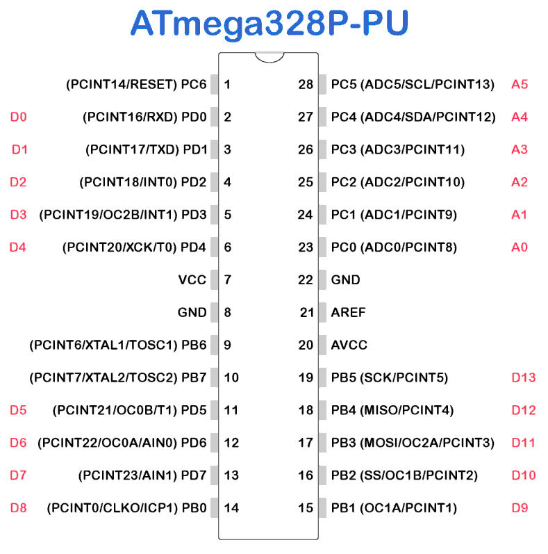
Figure-1:
Read the Datasheet!
Gammon is always an informative source:
Ok...
You might have noticed that there are two wildly different sets of answers showing up.
Are you talking about the connector labeled ICSP on the arduino boards, or the ICP1 pin described the the ATmega328 datasheet (but not used in usual Arduino code)?
I was referring to the later: The icp1 pin. It's not really clearly documented in most references. I understand it better after looking at the sample code.
So, that's probably the 3rd recommendation for @dth1971 to actually read the datasheet. Wonder if he'll get the hint?
A forum guru left icp1 code last year....
westfw on what it's for in 2014... post 2 of 2
From that post: It looks like you can configure things so that every time ICP1 changes state, the timer1 count at that time is copied to the "input capture register." Then you can read the register and get a time that the pin change occurred, potentially at a greater precision than you could in a SW loop looking at the pin...
Why read the docs when anyone can gp from clues and code they don't understand to do a half-fast job and get someone else to fix it?
Okay grumpy gusses. One thing I have learned over the years as a team lead and principal engineer is never chastice someone looking for help IF they are putting in an honest effort.
- I have 4 reference books here. Two by Simon Monk. Neither refer to this pin or it's purpose.
- I tried a google search and not that many return hits were available. Most referred to ICSP.
- I didn't know it's NOT part of the standard programming language as it's processor specific. And I didn' t have a link to the internals. And while I'll be reading it, even to most people, electrical engineers don't speak the same language as programmers, or aerospace engineers, or even mathematicians. So clarification by someone in layman's terms is always helpful.
Next time you come to me and you ask me how to do a Savitzky Golay noise reduction algorithm, or use AI vectors I'll tell you to "Read the docs" Its' fairly simple to understand and reduce down to computer algorithms:
Savitzky–Golay filter - Wikipedia
I'm creating a dynamically configurable multi sensor input/output that is custom configurable per unit. For example: Sensor X needs a regular IO pin +5V, GND, and an Analog in. It will assign pins based on priority of requirement. 54+! isn't a viable way to pick pins. (Mega digital IO) A key example of optimization here is picking a regular pin over a PWM pin. This will maximize the number of devices a single board can handle. As the ICP pin is something attached to a regular pin, I have to figure out how to prioritize it in these applications.
I am also writing a digital twin so I can debug arduino in a desktop environment before the code is uploaded using TDD techinques. As such I have to write digital twin equivalents, including for internals. I need to understand its purpose if I am to adequately simulate for the register and operation. As it's rising/falling edge event driving I can simulate it with thread locks, a stack push/pop and EventHandles or ThreadEvents.
I had no trouble finding explanations and code using the SEARCH on this forum. I linked some but nowhere near all of them, with answers.
But then I am not management material so I do expect people who are serious to look things up and make efforts to save themselves time.
When the docs are recommended SO MANY TIMES by people who will help with them and they won't even look.
You: "IF they are putting in an honest effort."
Myself and others: "I see a minimal effort to keep asking the same thing. I see no effort to ask better questions, only feed me's."
Honest effort would ask questions about specifics in the docs, not bleat "teach me everything personally".
Have you heard of Wokwi?
Have you worked giving FREE advice?
Are you trying to manage others who ARE?
We who have been doing so for years expect effort at the other end.
We don't get paid, so don't push. Let's see what you do here, besides try to "manage" us SJWhaaaaaa-style.
I don't think this sort of thing is as important as you seem to think.
Microcontroller pins typically have multiple functions, but the "basic GPIO" is almost always one them, regardless of what other functions are also available on that pin. So digitalWrite() and digitalRead() work fine on a PWM pin, in addition to analogWrite() (and the Arduino functions will switch the pins in and out of the proper modes as you use a function. (sometimes at significant cost. Sigh.))
So there is no reason to exclude the pin labeled ICP1 from other functions (like GPIO) that it can do. I guess it would be important to be able to allocate it to a sensor that needed ICP functionality, but if you had sensors like that, you'd probably know what it meant.
I didn't know it's NOT part of the standard programming language as it's processor specific.
It's a PIN. How can it not be processor-specific?
Since ICP is not a standard Arduino function, I am curious as to where you came across the term, that didn't include a more detailed explanation. Just scanning the schematic, perhaps? (although, it's not ON the Uno schematic...)
I am also writing a digital twin
What's a "Digital Twin"? Are you aware that there are several simulators for the AVRs (two from the vendor. One in GDB. A couple that are Arduino specific and include common peripherals (probably NOT ICP.)) A full simulation is a very significant project. (For one thing, the number of peripherals that are potentially operating asynchronously from the CPU instructions is ... quite large.)
I can software serial IO pins. It eats cpu cycles but I can!
But if I can use the UART, I'd much rather do that!
ICPx allows closer timing and counting with less blocking than soft-ICP doesn't it?