What is Ground in arduino?
And where should i connect the negative leg of a LED?L
Hi and welcome.
Ground or GND is where the electrical level is at 0 Volts.
It is mostly used as reference to all other electronic parts, they need one common point to operate correclty and that is usually GND.
If you are controlling your LED with a HIGH signal in your sketch, the cathode (negative leg) of that LED should be tied to GND
Do not forget to use a resistor between the other leg (anode) of that LED and the output pin of your Arduino.
MAS3:
Hi and welcome.Ground or GND is where the electrical level is at 0 Volts.
It is mostly used as reference to all other electronic parts, they need one common point to operate correclty and that is usually GND.If you are controlling your LED with a HIGH signal in your sketch, the cathode (negative leg) of that LED should be tied to GND
Do not forget to use a resistor between the other leg (anode) of that LED and the output pin of your Arduino.
Ok this is working, but i don't understand why should i connect to the ground?
Hi, gnd is an arbitrary reference point, on an arduino it is the negative of the power supply, it is used as REFERENCE POINT for all voltage measurements.
It is not really ground as in the stuff we walk on.
The cathode end of the LED usually designated K, will connect to gnd , the A or anode end will then connect to a supply via a resisitor or an arduino output via a resistor, the resistor is to limit how much current flows through the LED and arduino output.
There are other ways of connecting LEDs, check the "Learning" tab at the top of this page, and examples to see how to drive your LED.
As an example, when you measure how high something is or low, it is metres above ground or meters below ground, voltage is measured that same way with a point called gnd as the reference point.
Tom...... 8)
You are building a circuit.
If you put electrons at one side of a component, they still have nowhere to go.
You need to offer them an entrance, but also an exit in order to flow.
The output pin is the entrance to the LED.
The GND forms the exit.
It is important that you get this right, because you will have lots of trouble getting things to work if you don't.
So if this still doesn't help, keep asking (and tell us what you actually did understand).
That way we can work towards you completely understanding this.
Ok i understand.
Thank you
birkomester:
What is Ground in arduino?
And where should i connect the negative leg of a LED?L
"Ground" is a usually misused term.
Ground is the physical frame of an electronic device. Usually it is connected to the power line (mains) "ground" wire for safety.
The part of a circuit that is usually called "ground" by most people is "Circuit Common". It is typically the zero voltage point that everything in the circuit is referenced to.
For example, to control an LED with an Arduino, you would connect an Arduino port pin to a resistor and LED, then connect the other end of the LED to circuit common (called "ground" in most cases).
On an Arduino, this point is marked "GND" in the board's silkscreen. That is, the two pins between "5V" and "Vin" on one side, and the pin between "13" and "AREF" on the other side.
The negative side of most or all the components you use in a complete Arduino project will connect to circuit common (marked "GND").
The difference between "Circuit common" and "Ground" is this:
Imagine you built a project in a case with various components accessible by the user, an Arduino board inside and a power supply inside.
The structural frame of the case (if metal) as well as any controls that can be touched by the user would be connected to GROUND for safety. Most of the internal components of your project would be connected to their various pins and all return to CIRCUIT COMMON (called "GND" on the Arduino). The ground and the circuit common are not tied together, but are two separate, distinct points.
In most cases, the safety GROUND and the project's CIRCUIT COMMON would not and should not be connected together.
Lastly, think of ordinary house wiring or an ordinary power cord. You have two wires for power (black or brown for the "HOT" or "High Side" and white or blue for NEUTRAL (a.k.a. "circuit common"). There is a third GREEN or YELLOW/GREEN wire called GROUND which connects to the frame of the device (for safety) and it is a DISTINCT, DIFFERENT, SEPARATE wire from the white or blue "NEUTRAL".
Hope this helps (and isn't too confusing).
1 Like
There is a third GREEN or YELLOW/GREEN wire called GROUND
Well no it is not, not in the UK and Europe anyway.
That connection is called "Earth".
If you call it ground hen you are over using the word so do expect confusion.
To the OP, read this as to why you need a common reference point in a circuit.
http://www.thebox.myzen.co.uk/Tutorial/Power_Supplies.html
Grumpy_Mike:
There is a third GREEN or YELLOW/GREEN wire called GROUND
Well no it is not, not in the UK and Europe anyway.
That connection is called "Earth".
If you call it ground hen you are over using the word so do expect confusion.To the OP, read this as to why you need a common reference point in a circuit.
http://www.thebox.myzen.co.uk/Tutorial/Power_Supplies.html
OK... I didn't know it was also called "earth" (makes sense though!).
"Ground" and "Earth" are electrically the same thing... and the words even mean the same thing (earth, dirt, soil, ground, etc...)
But of course, "circuit common" or "common" is equally clear and easy to understand.
I was simply pointing out the fact that "ground", "earth" and "circuit common" (or "signal ground") are (incorrectly) used interchangeably.
As you know, there is even a schematic difference between the them......

Krupski:
Grumpy_Mike:
There is a third GREEN or YELLOW/GREEN wire called GROUND
Well no it is not, not in the UK and Europe anyway.
That connection is called "Earth".
If you call it ground hen you are over using the word so do expect confusion.To the OP, read this as to why you need a common reference point in a circuit.
http://www.thebox.myzen.co.uk/Tutorial/Power_Supplies.htmlOK... I didn't know it was also called "earth" (makes sense though!).
"Ground" and "Earth" are electrically the same thing... and the words even mean the same thing (earth, dirt, soil, ground, etc...)
But of course, "circuit common" or "common" is equally clear and easy to understand.
I was simply pointing out the fact that "ground", "earth" and "circuit common" (or "signal ground") are (incorrectly) used interchangeably.
As you know, there is even a schematic difference between the them......
A very concise description and clarification of a very confusing concept to explain to someone new to electronics theory. The fact that the terms are so often used interchangeably by people of all experience levels doesn't help.
To further confuse things, there is no clear consensus on what each of the symbols mean.
polymorph:
To further confuse things, there is no clear consensus on what each of the symbols mean.
Well at least we usually do have a consensus on what to call this. ![]()
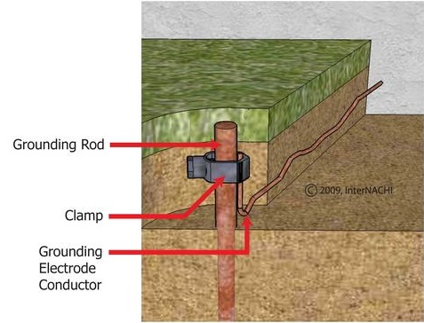
Well no, we in the UK would call that an Earthing rod.
Grumpy_Mike:
Well no, we in the UK would call that an Earthing rod.
But electronics should not be limited to applications just on this planet or would Marsing rod be unambiguous ? ![]()
And what would you call the metal casing of an electronic device on a space station? ]![]()
Good posts Krupski. For such a simple concept, ground can be pretty confusing to wrap your head around. Especially when there are so many names that sometimes, but not always, mean the same thing.
Afterall, ground/earth could mean mains or common. Vss could be common or -1 * Vcc, or something entirely different. To the OP: You start to get an intuitive feel for it eventually. Keep struggling through it until you do.
Earth should be renamed Vplanet!
"Vcc" (+5V) could be used as a reference, too - as long as you stay consistent, and everyone else is dialed in to that (very nonconformist.)
Anyway, LEDs (and their resistors) can be placed between an output pin and +5V, too.
Try that:
Use a sketch with a long HIGH time and a short LOW time and place the LED and resistor between the output and Gnd and then re-wire it with the LED between output and +5V.