Hi All,
I'd like to fit an RFID reader to my ebike for security. It's a 48V DC system and I need the apropriate relay to switch power to the "ON" button when the RFID fob trips the reader.
So I think what I need is a relay that takes 5V from Arduino/reader and opens 48V DC to the Display/ON button.
Everything I've seen is only 30V DC.
What might be a valid module part number?
Are you sure that 48VDC is applied to the Display/ON button? I would be surprised if so.
For informed help, please post a link to the bike and controller product page or data sheet. Forum members need more information about your specific wiring issue.
I'm not sure about the current. The display is fed 48V and I don't know about the circuit with the button. Even if that circuit was a normal 5v or 3v I'd prefer not to "mod" at the display but rather at the controller (more room) and I've already got a 5v 3A buck converter there. I beleive the MAX amp for the bike is 12A.
It would be a good idea to get out the trusty old multimeter and check voltages at various various key points. eBike control elements (like the throttle) and display electronics usually operate at 5V or less. There certainly could be exceptions, though.
Right now, forum members don't have enough information to do more than guess.
Most probably the board is fed from the main battery (48 V) and makes it's own 5V...
Good thing: it will have almost 0 current. Bad thing: you won't have 5V at your 5V pin if you break the 48V line.
I recommend to NOT put a relay in the 48V to motor line. At 12A it will be bulky and expensive. If you make an error you may set your house on fire (battery fires are not easily extinguished).
You can find inexpensive chinese SSRs on AE or Amz. Just search DC-DC SSR.
But that's likely not what you need. 12A is not going through this display circuit, neither through the "ignition" control wire.
I suggest you to study how the display/control-board works.
If your intention is to cut the power to the board, you could use this:
As others have said, you choose a relay by coil voltage, contact arrangement and contact capacity.
Don't try driving a relay from an Arduino board directly. It's always good practice to drive a transistor first and let that switch the relay coil. Also going to need protection in the form of a diode.
e-scooters do use 5-V DC on the throttle, or some do. The foot pedal versions find other uses in things like sewing machine speed controllers.
thanks to cattledog for reading and understanding my query and directing me to to the solution without going into details that while are important they are beyond the basic scope of the question. “What relay to use with a load of 48V and ~12A?”
And to Jim- Disconnecting the power prevents someone from tuning the bike on and running the motor with the wheel locked or changing settings.
It's not wrong to go to details, and people here generally try to help to avoid mistakes. You didn't provide sufficient information to get simple answer.
For example some (fake fotek) DC-DC SSR can be very ok for turning off the motor itself, but at the same time it might have noticeable leak current making it improper for turning off a control signal.
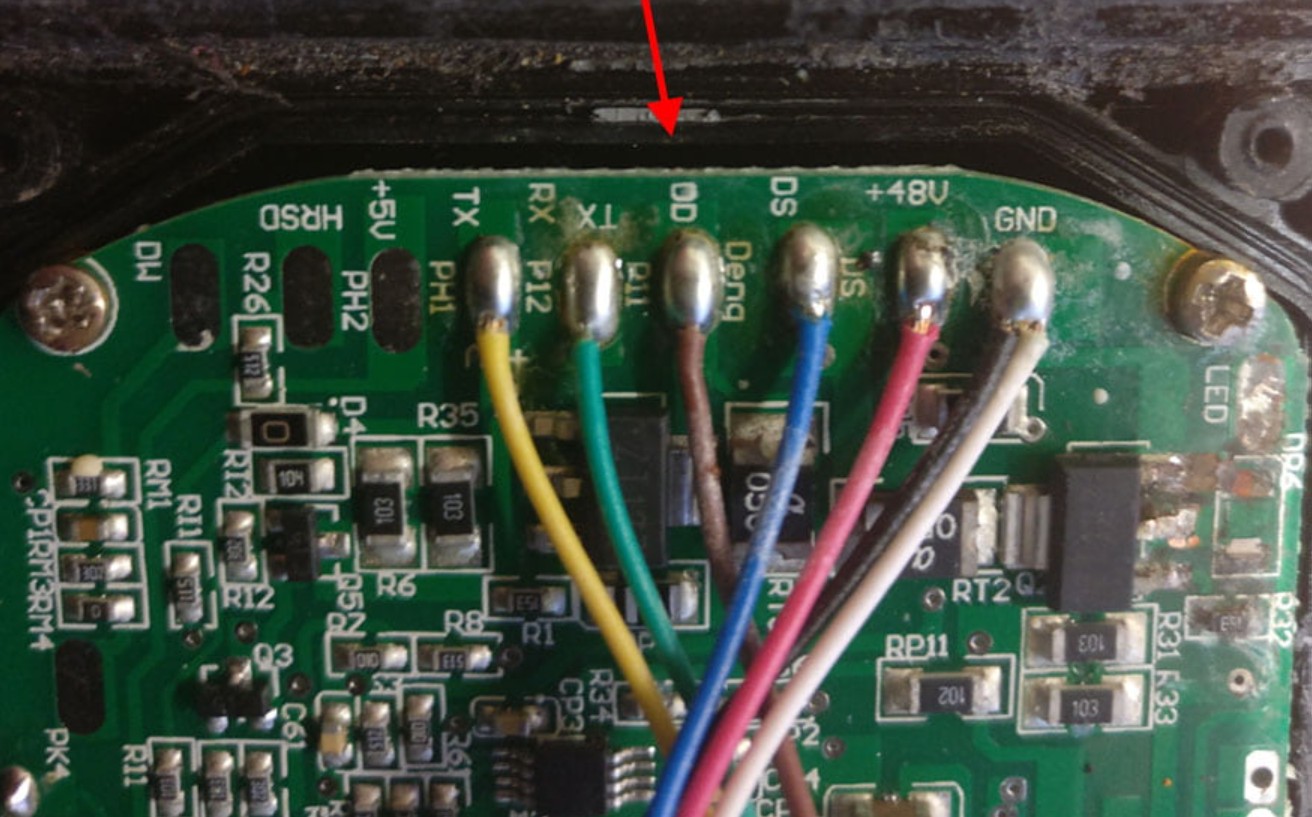
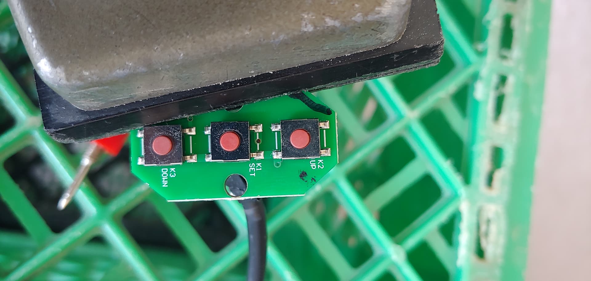
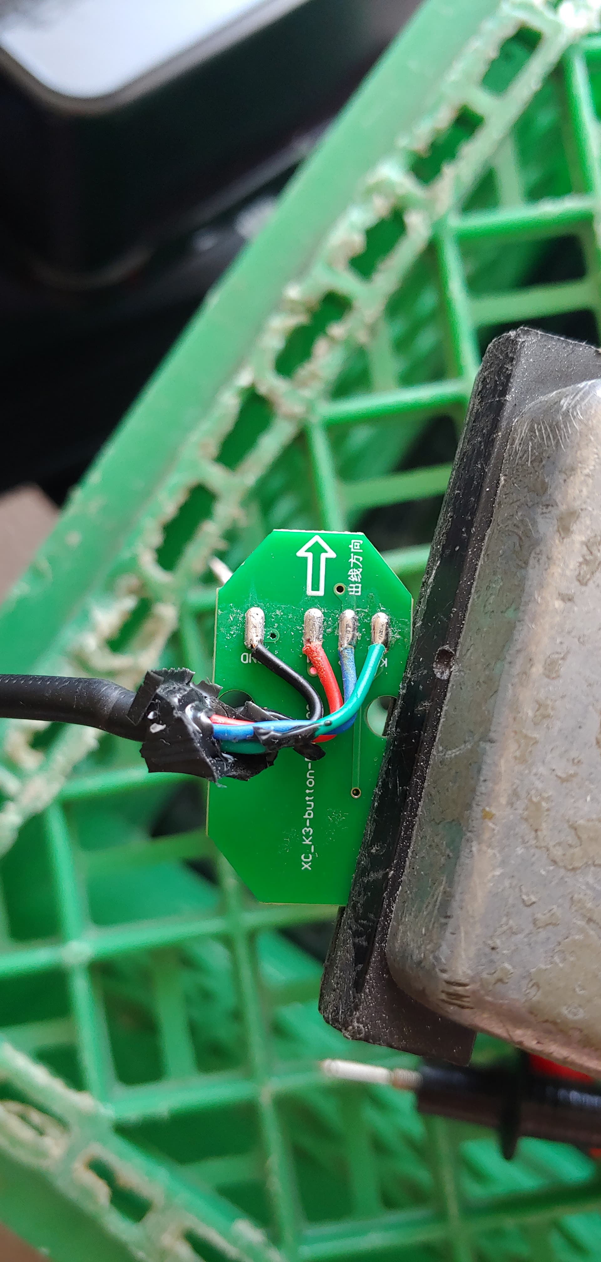
Back again with more details. I’ve got an ebike and to turn it on you press and hold a button (same to turn it off). This button also controls menu navigation. This button (M) is mounted on handle bar with two more buttons for“up” and “down” arrows as well as hold both to enter settings. The “M” button is fed with 45V and the arrows are both 0.750v. This control is wired back to the display which is fed 48V from the controller.
I’d like to instal a relay between the controller and display controlled by an RFID reader and a nano.
I got an RFID reader and a nano working to accept a fob swipe to open and close a relay but I’m not sure what relay I need nor do I know the amperage. The wire appears to be 20 gauge.