Ok so I am making a big seven segment display. This display will consist of 4 digits (4X seven segment displays) but I will be multiplexing them so one will only be on at any point in time.
The LED's I'm using have a forward voltage drop of 2.5v and are recommended to run at 20mA.
Each segment of each seven segment display will have 12LED's. So one seven segment display will contain. (7x12)+4. The 4 is for the decimal point. In Total it will contain 88 LED's.
In each Segment I will have 3 parallel lines each containing 4 LED's. Each parallel line will have a 100 OHM resister to "burn" the excess 2volts to keep current at 20mA.
So each segment will have a resistance of about 30 OHMs. For one seven segment display the resistance will be 4.7ohms. So basically one seven segment display supplied with 12v will draw 2.5amps when all 7 segments are turned on.
I will supply this displays power with a car battery which could easily handle 2.5 amps.
Firstly are my calculations correct?
And Secondly I plan to control this display with an arduino uno. So will I need transistors or relays to control this? Do you get transistors that can handle 2.5Amps?
I have Bc 547's which have a max voltage of 60v and 100mA which will definitely not work so what transistors can I use? Or must I use transistors and relays?
Each segment has 3 strings, so 3 x 20mA = 60mA per segment.
7 segments = 7 x 60mA = 420mA, plus decimal point = 440mA,
Since multiplexing that's it.
Relays are far too slow for multiplexing, and they wear out if driven like the clappers.
You could use a constant current LED driver chip like the STP16DP05 for the
low side (one channel per segment), and then PNP or p-channel transistor for
the high-side switching via a level-shifting stage. One such high side switch is used
per digit.
Darlington drivers will also work for low-side, such as the ULN2803, but don't
include serial-->parallel conversion so you might need a shift register as well to
save pins.
With a constant-current LED low-side driver you can lose the resistors, except that
you probably want some resistance to current-share better (or you could drive
each string separately from a constant current sink - most of these chips have
16 channels).
Correct me if I'm wrong, but you'll drive the "segments" individually . If you drive each segment with one transistor, maximum current per transistor won't be 2,5A , but only 3 times the current needed for a LED. -> 3x20mA = 60mA
And keep in mind that there will be differences of brightness between LEDs
edit : forget it, I was writing and didn't see MarkT's post, which answers the question
Each segment has 3 strings, so 3 x 20mA = 60mA per segment.
7 segments = 7 x 60mA = 420mA, plus decimal point = 440mA,
Since multiplexing that's it.
Relays are far too slow for multiplexing, and they wear out if driven like the clappers.
You could use a constant current LED driver chip like the STP16DP05 for the
low side (one channel per segment), and then PNP or p-channel transistor for
the high-side switching via a level-shifting stage. One such high side switch is used
per digit.
Darlington drivers will also work for low-side, such as the ULN2803, but don't
include serial-->parallel conversion so you might need a shift register as well to
save pins.
With a constant-current LED low-side driver you can lose the resistors, except that
you probably want some resistance to current-share better (or you could drive
each string separately from a constant current sink - most of these chips have
16 channels).
Thanx for pointing out my calculation mistake. I was deviding the 12v by the total resistance instead of dividing the 2v by the total resistance. So 2v/4.7ohms=425mA.
I'm don't want to use a shift register. I have already connected my arduino to a 4 digit seven segment display and it displays perfectly.
The only difference now is I'm moving to a bigger one which requires more current which my arduino cannot handle. Thanx for your opinioun on how I can change my entire setup but no thank you. I am using multiplexing.
For Alnath
I'm not driving each segment separately, I'm driving each seven segment display digit separately. I was made aware of my calculation mistakes though.
Ok so I can't use relays as they are too slow. Thanx for that. So what transistors can I use that will use a digital on/off signal from my arduino on the base to make 12v at 425mA flow from collector to emitter? As simple as that? Please I don't wana hear about shift registers and and, I'm not being cheeky those things are just abit outof my league for now as I am a beginner and I want to just use transistors which are fed signals from my arduino on/off to make the higher powered circuits turn on and off.
This display will consist of 4 digits (4X seven segment displays) but I will be multiplexing them so one will only be on at any point in time.
So you need 7 current sinks that connect to each segment in parallel that can sink 60mA each, and PNP or P-channel MOSFETs that can source 7 x 60mA or 420mA each.
Or, 7 current sources capable of 60mA each, and 7 NPN or N-channel MOSFETs that can sink 420mA each.
Personally, I'd go with TCIP6B595 for current sink, simple SPI.transfer() to setup the cathodes:
digitalWrite (RCKpin, LOW);
SPI.transfer(fontArray[digit_to_display]);
digitalWrite (RCKpin, HIGH);
and Logic Level, low Rds, P-channel MOSFETs for current sources:
This display will consist of 4 digits (4X seven segment displays) but I will be multiplexing them so one will only be on at any point in time.
So you need 7 current sinks that connect to each segment in parallel that can sink 60mA each, and PNP or P-channel MOSFETs that can source 7 x 60mA or 420mA each.
Or, 7 current sources capable of 60mA each, and 7 NPN or N-channel MOSFETs that can sink 420mA each.
Personally, I'd go with TCIP6B595 for current sink, simple SPI.transfer() to setup the cathodes:
digitalWrite (RCKpin, LOW);
SPI.transfer(fontArray[digit_to_display]);
digitalWrite (RCKpin, HIGH);
Ok dude u are talking greek to me. I don't know what u mean when you say current sinks. I dont know why people have to use such big phrases and words. I have already written my program so that's all good. My program switches grounds between each seven segment digit every 5 milliseconds to display the number. (Multiplexing). It works and I have tested it multiple times so I'm not changing my program.
Can anyone tell my why a 2N2222 will not work?
Looks like ill have to draw a picture so u guys can see its something simple. F me
You are proposing to drop 10V in the LEDs and just 2V in the series resistor. That doesn't give you a lot of headroom for the current regulation. If the battery voltage drops by just 5% to 11.4V, the LED current will drop by about 20% (four times as much). Similarly if the battery voltage rises by 5%. In practice, you will also have the voltage drop of the segment and digit drivers to consider as well, unless they are mosfets with low Rds(on), and this will make things even worse. So you may wish to use 4 strings of 3 LEDs instead. However, a car battery provides quite a stable voltage as long as you are not charging it at the time, so you may consider the performance with 3 strings of 4 LEDs acceptable.
For the low-side drivers, what you need ideally is an octal driver chip with open-drain mosfet outputs. I don't know of any such chip. The TPIC6B595 suggested by Crossroads is a shift register with high-current open-drain outputs, which makes it a good choice. I wouldn't recommend the ULN2803 if you are using strings of 4 LEDs, because of its high saturation voltage. The 2N2222 also has poor saturation characteristics. BC337 would be better.
For the digit drivers, you need e.g. an NPN transistor followed by a PNP transistor or P-channel mosfet, because you need to level-shift the drive to +12V. Mosfets would be best, and as they don't need to be logic level in this case, you have a wide choice. However, as the switched current is only 420mA max, you could get away with a PNP transistor such as BC327 instead.
Will you be making a PCB, or wiring it up on perfboard, stripboard etc.? That makes a difference to my recommendation, because SMD mosfets cost much less than through-hole ones.
EDIT: the above assumes that you wire the displays as common anode, because that means you need one level-shifting driver per digit, instead of one per segment.
calvingloster:
Ok so I can't use relays as they are too slow. Thanx for that. So what transistors can I use that will use a digital on/off signal from my arduino on the base to make 12v at 425mA flow from collector to emitter? As simple as that? Please I don't wana hear about shift registers and and, I'm not being cheeky those things are just abit outof my league for now as I am a beginner and I want to just use transistors which are fed signals from my arduino on/off to make the higher powered circuits turn on and off.
If you want to fully saturate a 2N2222 with an Ic = 0.5A , you'll need almost Ib = 50mA (which is too much for the arduino outputs), and you'll have Vce(Sat) = 1V .
IMHO, as CrossRoads said, a logic level Mosfet would be a better choice . You won't have to change your code... P-Channel or N-channel depends on your design. So, yes, a schematic would help to help you...if you still want to be helped....
I don't know why people need to be aggressive against people who help them
I have already written my program so that's all good. My program switches grounds between each seven segment digit every 5 milliseconds to display the number. (Multiplexing).
You need to help us out a little, and learn a little terminology.
A current source provides current into a circuit - like a 12V supply
A current sink provides the path to Ground for the current.
An LED (or string of LEDs) with anode connected to +12 has current sourced from +12 supply - if there is a transistor between +12 and the anode, the transistor is the current source.
An LED with cathode connected to ground has its current "sunk" - if there is a transistor between cathode and ground, the transistor is the current sink.
Those transistor might be built in to another device as well.
Now, Arduino can't control 60mA & 12V per segment directly. It will not be connected to the LEDs at all.
You seem to have some sort of multiplexing planned - how are you switching between which digit gets turned on?
Typically, all the A segments get turned on parallel, all the Bs, etc. from either the anode side, or from the cathode side.
If the anodes are all in parallel, then each digit will have a common cathode, and the multiplexing is done by connecting one common cathode to Gnd at a time.
If the cathode are all in parallel, then each digit will have a common anode, and the multiplexing is done by connecting one common anode to +12 at a time.
Now, you say "My program switches grounds between each seven segment digit every 5 milliseconds to display the number." So that seems to explain the cathodes - what is happening on the anode end of the LED strings?
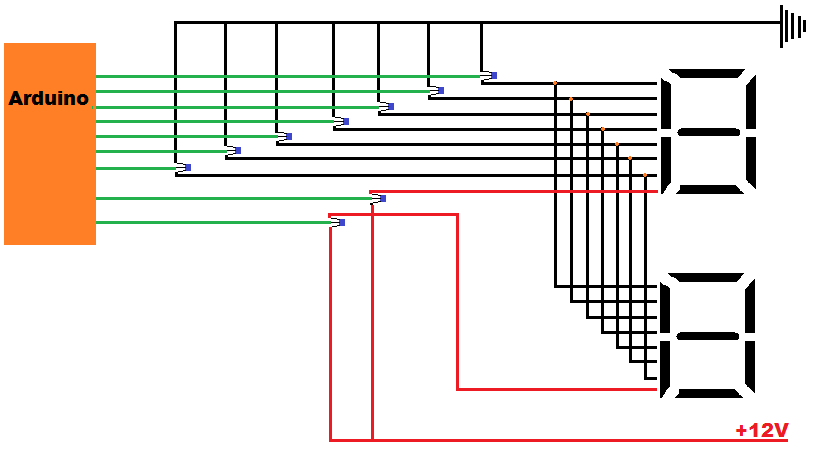
The picture i have attached is what i want to do and by the looks of this and what you guys are telling me is that it wont work without some hectic use of electrical engineering knowledge and chips and stuff :(. Im sorry i am very frustrated but i think i jumped in too deep with this being my first project ever. I started reading up about electronics like 4 weeks ago. So i apologize if i seam aggressive, you guys are just way too knowledgeable on this unlike me. With the knowledge i have i want to just simply use transistors like in my diagram but i guess i cant and i dont know why it cant work but anyways. The display is common anode, that is all the positive leads are connected and displays are switched by switching the corresponding ground. I only drew 2 SSD's but there are actually 4. But two explains the cuircuit
Ok i am a bit confused and i think my drawing is wrong but it still explains what i wana do with the transistors. When i wired my arduino directly to the small SSD's all the grounds of the four displays went into 4 different pins. Then the 7 positive leads went into 7 pins on the arduino. So if i wanted to switch display 1 on i will set the ground as low and the the positive pins as high according to which number i want to display.
calvingloster:
Ok i am a bit confused and i think my drawing is wrong but it still explains what i wana do with the transistors. When i wired my arduino directly to the small SSD's all the grounds of the four displays went into 4 different pins. Then the 7 positive leads went into 7 pins on the arduino. So if i wanted to switch display 1 on i will set the ground as low and the the positive pins as high according to which number i want to display.
So your display is wired as common cathode. If you keep it that way, then you need 8 level-shifting high side drivers, and 4 of the simpler low-side drivers. If you wire your new display as common anode instead, then you need 4 level-shifting high side drivers and 4 low-side drivers.
Or you could forget about multiplexing them altogether, and just use 4 x TPIC6B595 to drive all the display cathodes individually - no need for high side drivers that way.
you see this is what grates my tits, if you want to go show your knowledge off go do it on another place. i have asked a question, if you cannot answer the question then don't post a comment. you are not helping at all? are you just trying to get your post count up or what? i am not asking how i can make my circuit more efficient or how to use less pins, please dude stop now with your shift registers for the millionth time
What you have is fine, and you are definitely on the right track.
For the common anodes you need PNP, or P-channel MOSFETs.
You will turn on one common anode at a time.
For the parallel segments, you need NPN, or N-channel MOSFETs.
You will turn on the NPNs for the digit you want displayed.
Now here's the tricky part: PNP, or P-channel MOSFETs, need their control pin pulled low to turn them on, and high to turn them off. High in this case means 12V.
To do that, you will have a resistor from 12V to the control pin.
The arduino output pin can't go to 12V, tho, so the arduino will control an NPN transistor, and that will pull the PNP/P-Channel control pin low.
NPN emitter connects to Gnd, collecter to PNP/P-Channel - high from Arduino into NPN turns it on, which bring collector low and turns on the anode supply pin.
I also suggest you back off on the attitide with other posters, that is no way to make friends.
CrossRoads:
What you have is fine, and you are definitely on the right track.
For the common anodes you need PNP, or P-channel MOSFETs.
You will turn on one common anode at a time.
For the parallel segments, you need NPN, or N-channel MOSFETs.
You will turn on the NPNs for the digit you want displayed.
Now here's the tricky part: PNP, or P-channel MOSFETs, need their control pin pulled low to turn them on, and high to turn them off. High in this case means 12V.
To do that, you will have a resistor from 12V to the control pin.
The arduino output pin can't go to 12V, tho, so the arduino will control an NPN transistor, and that will pull the PNP/P-Channel control pin low.
NPN emitter connects to Gnd, collecter to PNP/P-Channel - high from Arduino into NPN turns it on, which bring collector low and turns on the anode supply pin.
I also suggest you back off on the attitide with other posters, that is no way to make friends.
Thanx that makes sense, although I don't understand why I must put a resister between the 12v and the control pin?
calvingloster:
you see this is what grates my tits, if you want to go show your knowledge off go do it on another place. i have asked a question, if you cannot answer the question then don't post a comment. you are not helping at all? are you just trying to get your post count up or what? i am not asking how i can make my circuit more efficient or how to use less pins, please dude stop now with your shift registers for the millionth time
Hey, take it easy, and don't be so rude. You came here looking for help and advice, people have taken time to answer you and give you advice based on years of experience and you throw it back at their face.
Instead of brushing up on your electronics, I suggest you start with a basic course in manners.