I am trying to setup a wheatstone bridge to make a ohmmeter that can calculate the resistance between 0.5ohm to 3ohms. My voltage I intend to provide is 3V because I want to eventually use a light blue bean arduino for my project.
I understand how wheatstones work (at least on a basic level) but I don't understand how to use it to calculate the resistance. I could use analogRead() to get two different voltage values but am unsure how to actually use it.
Based on the picture on wiki, , I can setup the arduino to read the voltage value between R2 to ground and Rx to ground. But can someone help me with the math?
A bridge offers you no advantage when used on an arduino like this. Discard half of it and just have R1 and R2.
Then the maths is just a potential divider, you know R1 you know the voltage so measuring the voltage at the junction you can work out the resistance by ohms law.
The way a Wheatstone bridge is usually used is that the variable resistor (R2 in your circuit) is adjusted until the voltage reading, Vg, becomes zero. The value of the unknown resistor Rx is then given by:
Rx = R2 x R3/R1
As Mike pointed out it isn't very practical to do that with the Arduino. You need the variable resistor R2 to be accurately calibrated.
How accurately do you need to measure the resistance? To measure the voltage across a 0.5 ohm resistor with any reasonable accuracy with the analogue inputs of the Arduino you would need to supply a high current unless you use an op-amp to give some voltage gain.
the wheatstone bridge is the firs half of the circuit.
the voltage out is often a very small scale output and a (pick one) [ op-amp][instrument amp][differential amp] will then allow you to change the value into something more useable.
a quad op-amp will allow you to have one for setting the zero, another for setting the span, and a third for the actual amp.
once you start to look at op-amps and wheatstone bridges, you find that often a signal is strong enough to use with an op-amp alone.
the reason for the zero and span is to set your range to be as close to the analog/digial converter (ADC)as you can.
last bit is the span of the ADC. if your span is as close to the full range of the ADC in the bean, then you will get more resolution.
lastly, there are some op-amps that require both + and - input power
some that require about 2 volts more power than they can ouput, sucks when you power it with 3 volts and your output is between 1.5 and 1.5 or worse.
for your application, you would want a near-rail-to-rail. the closer you get to a true rail-to-rail the more expensive the op-amp.
I would check with the blue bean community to see what is common or available in that form factor.
russellz:
The way a Wheatstone bridge is usually used is that the variable resistor (R2 in your circuit) is adjusted until the voltage reading, Vg, becomes zero. The value of the unknown resistor Rx is then given by:
Rx = R2 x R3/R1
As Mike pointed out it isn't very practical to do that with the Arduino. You need the variable resistor R2 to be accurately calibrated.
How accurately do you need to measure the resistance? To measure the voltage across a 0.5 ohm resistor with any reasonable accuracy with the analogue inputs of the Arduino you would need to supply a high current unless you use an op-amp to give some voltage gain.
Russell.
It needs to be accurate up to +/- 0.2ohms. The range would be between 0.5 ohms to 3 ohms. Using a simple voltage divider, the data is so inaccurate that I thought I should try something better. But that was when I tested to see how close it could get to measuring a 100ohm resistor using 10k as the other resistor.
It needs to be accurate up to +/- 0.2ohms. The range would be between 0.5 ohms to 3 ohms.
so that would be +/- 40% at the low end and 6.6% at the top end, not very demanding.
Using a simple voltage divider, the data is so inaccurate
No you have a 10 bit A/D here so you have 4.88mV sample size, more than enough for what you say you need.
Your major problem is the current you need to drive through these low resistors to get these readings has to be I suspect too large. That is not going to change with a Wheatstone bridge.
It looks like you will have to use other measures, like amplifying with an op amp, or using your unknown resistor as a component in an oscillator and measuring the frequency.
Feed 10mA through the resistance which gives you 5mV to 30mV, amplify it by 100 using a couple of Op Amps as you should not try to get 100x gain in one stage.
0.5 ohm becomes 0.5V, 3 ohms becomes 3V. You'll either need a good Op Amp that can go right down to 0V with a single supply, or a negative supply voltage available for the Op Amp. It is fairly simple to generate using a pin on the Arduino to drive a voltage doubler wired as a voltage inverter, with an LED acting as a simple 2V zener diode to get a -2V supply. You could include circuitry to null any input offset voltage, or just measure it and take it into account when calibrating via software.
5V/10mA = 500 ohms
You can simply use 470 ohms and calibrate accordingly. You have to calibrate anyway.
0.5 to 3 ohms will only cause a change in current of:
5/(470 + 0.5) - 5/(470 + 3) =
10.627mA - 10.571mA = 56.168uA
Or a drop of only about 0.5% in the reference current from 0.5 ohm to 3 ohm. Not much point worrying about that.
In any case, as long as 5V supplying that resistor is also Vcc, variations in that won't affect the readings as both the divider network and the ADC will be using the same reference voltage.
polymorph:
0.5 ohm becomes 0.5V, 3 ohms becomes 3V. You'll either need a good Op Amp that can go right down to 0V with a single supply, or a negative supply voltage available for the Op Amp. It is fairly simple to generate using a pin on the Arduino to drive a voltage doubler wired as a voltage inverter, with an LED acting as a simple 2V zener diode to get a -2V supply. You could include circuitry to null any input offset voltage, or just measure it and take it into account when calibrating via software.
What do you mean that 0.5 ohms will become 0.5V?
Also, I need to use 3V, not 5V.
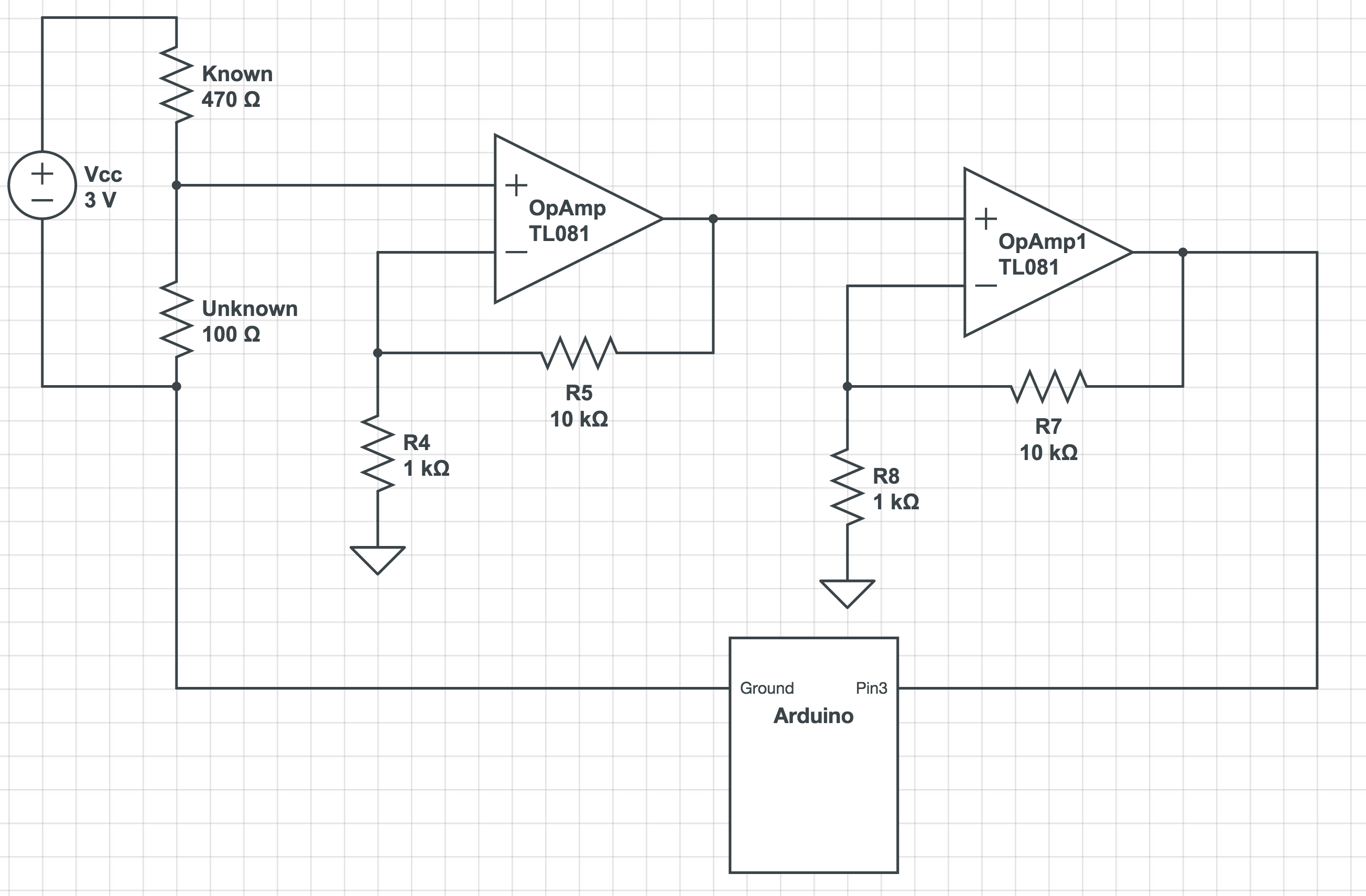
If I understand what you are saying, are you suggesting something like this? Ignore the resistance values or the name of the opamp. If I understand opamps correctly, the values of r4 and r5 will be able to dictate how much I boost the value of the voltage recorded.
Yes, except that the Arduino is reversed - The output of the Op Amp needs to go to A0, and the lower side of Unknown needs to go to the Arduino ground. Known R is 470, Unknown is your 0.5 to 3 ohm. So roughly 5mV with 0.5 ohms, 30mV with 3 ohms.
Then two Op Amp sections wired up as non-inverting as shown. R4 1k, R5 10k gives you a gain of 11 in a noninverting configuration. Or you could get a 9.1k resistor for R5. Then follow it with another Op Amp wired the same way.
So the first Op Amp then puts out 50mV at 0.5 ohms, and 300mV at 3 ohms. Second Op Amp puts out 500mV at 0.5 ohms, and 3V at 3 ohms.
Imgur won't post as an image, you have to do it as a link.
I think you might have misunderstood my confusion. I noticed that there are many different types of amps and am not sure which one to purchase. What attributes should I look for?
Mastermind, the circuit you have drawn gives you 0.5 V across the 100 ohm resistor. The output of the second op amp is thus trying to be 50 V which it can't do! With your 3 ohm resistor there though it should work.
Why not use the 5 V Vcc from the Arduino and change the 470 ohm resistor to 47? Then you could just use one 10 x gain op amp stage.
You will need +ve and -ve supply rails for those op amps.
Russel, that was my mistake, the unknown resistor is somewhere between 05 ohms to 3 ohms.
This project I am working on is a bluetooth enabled device. I have only been able to find one successfully launched Bluetooth PIC, the LightBlue Bean. However, it is severely limited in what it offers and it only offers 3V.
I really wish the blueduino had been more successful but it seems that it either isn't sold anymore or never actually started selling.
Is anyone else aware of any bluetooth enabled arduinos that are small?
You have to be very careful when you type in numbers.
0.5 to 3 ohms is what mastermind meant to type.
OK, so is the Arduino running from 3V? That's fine. Using 3V also to supply current through the 470 ohm resistor means the voltage is scaled down, too. 19mV at 3 ohms will result in about 2V at the output of the second Op Amp stage.
A clarification on the word "amps": in this context, he means "amplifier".
You use two Op Amps because generally you don't want to try and get a voltage gain of 100 in one stage. It is simple enough to use two Op Amp stages.
The TL081 will not work unless you supply it with at least +5V -and- -5V. It is not rail-to-rail, nor is it well suited to a single supply low voltage.
The ubiquitous LM324 is not well suited, as the output can only go to a voltage 1.5V below the supply voltage. You should pick out a RRIO Op Amp, something rated to run down to 2.5V single supply voltage. It doesn't have to be fast.
mastermind:
I think you might have misunderstood my confusion. I noticed that there are many different types of amps and am not sure which one to purchase. What attributes should I look for?
op-amps come in a huge variety.
to give some very general classification, some require both a positive and a negative voltage. this allows them to have power at zero and even go negative. AC vales from some devices can be measured.
next, some require power to do anything. if you have a 12 volt input, it consumes voltage and will nor work at a 0 volt in and it will not output more than about 10 volts. in other words the workable range is the 60-80% between the supply power voltage.
to narrow the range further, you want something that is near rail-to-rail. that means if you feed it 3 volts, the output will be near 0 to 3 volts. 'near' is the key. the closer you get to the rails, the more expensive the chip.
not sure what suppliers you can choose from, search your favorites for a rail-to rail to get an idea what is available. often, those like digi-key will show quantities available. often the fact they have hundreds or thousands means that it is available at any time. better chose than one that has the exact same spec but no one stocks it.
Measuring low value resistances accurately means passing a known/constant current
through the device and measuring the voltage across it (using a 4-terminal connection).
For best results a fairly large current is needed (be careful of self heating though)
so that the voltage can be measured accurately. Using an instrumentation amp
is a good idea to give high performance in the voltage measurement - this is inherently
a differential measurement so you must use a differential amplifier configuration.
MarkT:
this is inherently
a differential measurement so you must use a differential amplifier configuration.
And of course, a differential measurement actually is in effect, a Wheatstone bridge!
If accuracy is not paramount, an LM386 is in fact, an IC inherently configured to provide this function with an absolute minimum of external components. However 3V operation - for any op-amp - is a bit of a stretch.