I have a TTGO T-watch-2020-V1.
Until recently, I was able to upload my programs without problems.
But now, I get this error:
esptool.py v3.1-dev
Serial port /dev/cu.usbserial-0200D10B
Connecting…………………_____
A fatal error occurred: Failed to connect to ESP32: Timed out waiting for packet header
A fatal error occurred: Failed to connect to ESP32: Timed out waiting for packet header
I have searched via google and found several solutions.
People on the internet suggest to hit the reset button or the enable button. But the watch does not have these buttons.
People on the internet suggest to take GPIO pin 0 low and to solder resistances and capacitors from one pin to another.
Can anyone help me find these pins?
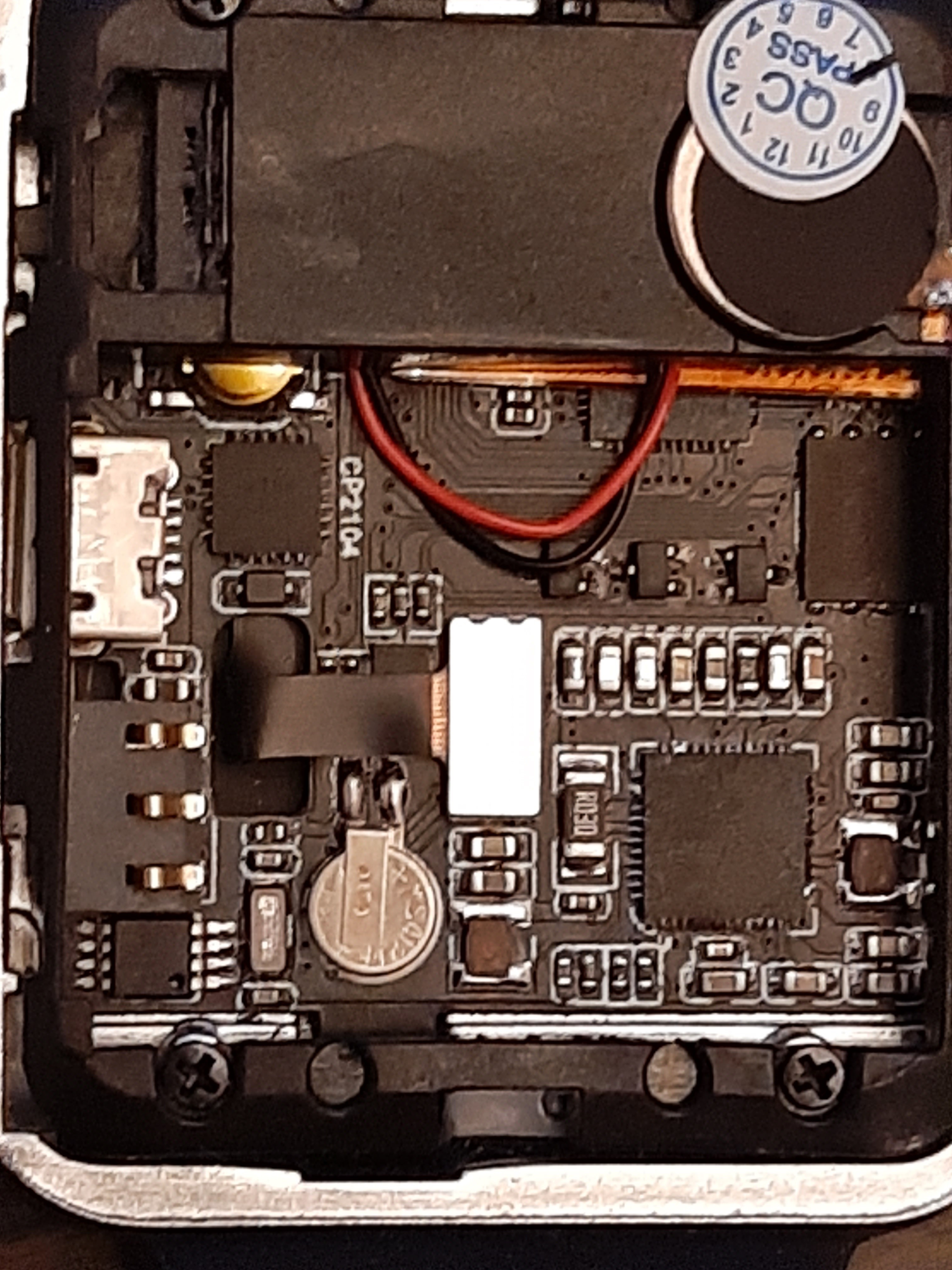
I made a picture:
I see an indication of CP2101 (the USB to UART bridge), but no chip with ESP32. I would expect such a chip to have some indication of how to position it (when you want to put it on some board) (a dot or an indent), but I do not see any of that. So: where is my ESP32, and how can I find out the orientation of the chip. Or is the ESP32 chip somewhere hidden on the other side of the print?
Hi,
ESP32 chip is located under the speaker and touch screen flex cable. On your first picture you can see part of it under the red an black speaker wires.
But first try to hold down power button during whole sketch uploading (or rather about 5 seconds before uploading starts). It worked for me, when I was in similar situation.
Hope it did help.
Edit: There is also partially hidden button covered by the speaker above usb connector which i belive is reset.
I have unscrewed and lifted the black plastic cover and used a magnifying glass to look for the ESP chip.
The ESP chip is not in the red circle. It is halfway hidden just below where the black and red wire go below the plastic cover on the right. I think GPIO0 is the pin left from the most right pin on the fully exposed row of pins of the chip. It seems this pin is connected to the reset button, but it is quite difficult to follow the tiny tracks. The reset button is where the black and red wire go beneath the plastic on the left. It is a bit yellowish.
Unfortunately pressing this button did not solve the upload problem with my new Mac computer...